Simple Quality Control Testing
Introduction
Quality control is a component of Quality Assurance and is by defined the National Council on Radiation Protection and Measurements (NCRP) as
"a system of monitoring, evaluation and maintenance at
optimal levels of all characteristics of performance that
can be measured and controlled" (NCRP99, p3).
The quality control procedures detailed on this page are specifically designed to be quick, simple and cheap- they are therefore limited in their sophistication. The tests are specifically for film/screen radiography. The test results should be seen as indicative rather than quantitative. These quality control tests are most suitable for remote area radiography services where there is no sophisticated testing equipment. The sample images on this page were taken from a workshop in Papua New Guinea(PNG) in which three-room X-ray departments were subject to quality control testing. There was no digital imaging in PNG at the time.
It would be useful to eliminate as many variables as possible when undertaking these tests. For example, use film from the same box and use the same cassette. It would also be advisable to consider the effects of the anode heel effect.
Your eye can pick up density changes of around 25%. If you can see a difference in the test film density, you would expect the difference to be at least 25%.
Fixed X-ray Machine Testing
Testing Setup
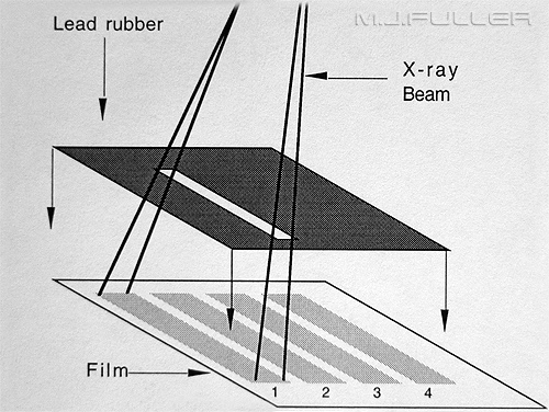
The following fixed X-ray machine tests are set up in a very similar manner. They involve making multiple exposures of an aluminium test wedge. It is important to ensure that the scatter radiation from one image does not affect the adjacent image. The following are suggested.
- cone within the edges of the step wedge
- use a thick lead or lead rubber mat as shown
- place a piece of lead or lead rubber behind the cassette to reduce back scatter
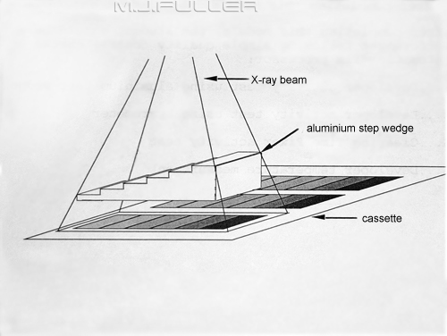
It is better to use an aluminium stepwedge to assess the relative exposure densities. The step wedge will allow you to use a variety of exposure settings. If you don't use the step wedge the exposures you can use will be very restricted.
If you don't have a step wedge, you may be able to construct one using layered up strips of aluminium. Alternatively, use any object that will give you an image with a range of densities.
Viewing Setup
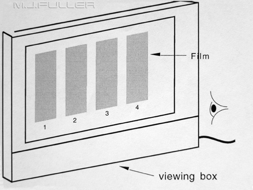
The test images that are produced can be assessed using a viewing box or with a sensitometer. A sensitometer will be more exact.
Room Comparability Testing
In a three room X-ray department, it is very useful to know the exposure comparability between rooms. These three test images were taken using identical exposures and related factors. The same aluminium step wedge was used for every exposure. There was no densitometer in PNG- all assessments are purely visual. It appears that rooms1 and 2 demonstrate good comparability for the exposure factors used. Room 3 demonstrates a slightly higher optical density, but this is visually minimal. The results cannot necessarily be extrapolated to the point that all exposures can be said to be comparable across the three rooms. However, further testing using different exposure factors would provide further information and confidence.
Care should be taken to avoid scatter radiation overlap.
Exposure Consistency Testing
This is a very simple test. If you expose a film using identical exposure and related factors, are you achieving a consistent film density?
This test image demonstrates satisfactory density consistency for the exposure factors employed. A very short exposure time was deliberately used- errors in the machine timer are more likely to show at short exposure times.
Care should be taken to avoid scatter radiation overlap
This test could be undertaken without an aluminium filter. You should aim for an optical density of about 1. Your eye is sensitive to differences in density at this level. An optical density of 1 is light enough to read paper print through the exposed film.
The only legislative regulation I could find required that the standard deviation of 5 consecutive exposures (70 kVl, 20mAS) divided by the average of the 5 exposures should not exceed 0.05 or 5%
Exposure Linearity Testing
This test attempts to establish if the same film density is achieved using the same kVp and mAS but different mA and time values.
The results suggest that there is some error in this machine's mA linearity. Until such time as the machine is serviced, the lack of linearity can be taken into consideration in exposure setting. If there is a large error at one of the mA values, this mA should be avoided.
Care should be taken to avoid scatter radiation overlap.
This test assumes the followingTesting should be undertaken on broad and fine focus
- the timer is accurate and consistent
- kVp is consistent
- processing is consistent
Phototimer Chamber Testing
This is a simple test designed by Anne Paris (Superintendent Radiographer, Northwick Park Hospital, London). The test is aimed at assessing whether the same exposure is achieved irrespective of which phototimer chamber or combination of chambers is used.
The test uses MDF panel, but this could be substituted with any other suitable uniform material.
The chambers are tested individually with identical exposure factors and coning. The only changes that are made between test exposures are to change the cassette and to select a different chamber/chambers.
As with most of these tests, the resulting film density is best tested with a densitometer. If a densitometer is not available, visual testing will provide useful indicative information.
This test setup could also be used to assess phototimer consistency.
Paris, A. Design of a Hardboard phantom used to check the consistency and accuracy of radiographic automatic exposure device". Radiography. Sept/Oct, 1985 Vol51, No 599
Light Beam Diaphragm Alignment Testing
This test aims to assess how well the light from the LBD matches the primary X-ray beam.
You could place an arbitrary level of acceptance or there may be legislative levels of acceptable error. In practice, if you are repeating views because of LBD alignment errors, a fix is required.
Below is one legislative regulationInterestingly, if the X-ray beam is marginally outside the light beam, the increase in patient dose is also marginal. If an image is repeated because the X-ray beam is inside the light beam and cuts of critical anatomy, the dose to the patient for that view is doubled."a. The primary X-ray beam must not exceed the light field and
b. The edge of the primary X-ray beam must not fall more than 10mm inside the light field at a focus-film distance 0f 100cm"
Processor TestingFixer Clearing time Test
The aim of this test is to asses the fixer solution activity level. If the fixer is in need of changing, the archival value of your radiographs can be diminished severely. Don't wait until your images start to look milky.
A sample of fixer is taken from the fixer bath of the processor and poured into the flask. You might be able to use the processor drain valve, but let it run for a while before taking the sample to clear the line.
Drop a strip of unprocessed film into the fixer and time how long it takes before you can read the newspaper behind. Compare this clearing time with a reference test with newly mixed fixer.
Previous testing has found an average clearing time of approximately 11 seconds.
Developer Activity Test 1
This is a crude method of monitoring the relative developer activity levels in your film processor. A test film is produced be exposing a 35x43 film multiple times. After each exposure the lead strip is pulled back. Don't expose the last strip- leave it unexposed. This process is repeated until you have achieved a suitable number of density strips. The exposure used needs to be very small- 180cm ffd, 60kVp, 2mAS, 400 speed film. The cassette is taken into the darkroom and the film is cut into strips.
The test strips are kept light safe and radiation safe.
A reference test strip can be processed after the chemistry is changed in the processor. A periodic test strip put through the processor will give you some idea as to how far the developer has reduced its activity level relative to the reference strip.
You should end up with a series of strips that look something like this. Processing a strip every day may be excessive. Equally, once a week may be too infrequent.
Developer Activity Test 2
A thermometer and a hygrometer can be very useful for testing the developer in your processor.
Check the processors operator's manual for the optimum developer temperature.
Check with the chemical supplier for the acceptable range of specific gravity values for the developer.
Other Testing
Screen Type and Speed Testing
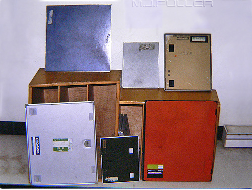
If your cassette collection looks like this, you may have a number of quality control issues.
Firstly, you should establish whether you are using blue light sensitive film or green light sensitive film. If you are using blue light sensitive film, it must be matched to cassettes with blue light emitting intensifying screens. A simple test is to open the cassettes and irradiate the screens in a darkened X-ray room. You might need a largish exposure to appreciate the colour emitted from the screens.
The symptom of mismatched screens and film is an inability to achieve sufficient density despite increasing your exposure.
Once you have a uniform set of cassettes, establishing the speed of the screens is important.
To test the speed of the screens in your cassettes it is useful to have a reference cassette(s) of known screen speed. It would be common to have regular screens that have a speed of 400 and detail screens with a speed of 80-100. A test can be carried out by placing the reference cassette and the cassette to be tested next to each other and exposing the cassettes together. The test exposures should be coned into strips using mAS values of 2,4,8,16 and 32 mAS.
Process the films and place the films next to each other. If the screens are the same speed, the densities at each mAS will match. If they do not match, you can assess how many exposure steps they differ by.
If you do not know the speed of any of your screens, do a step wedge test of all cassettes using the same exposure settings and parameters. This should give you an indication of which screens match and the relative differences in their speeds. It would be useful to have two speeds only.
Lead Gown Testing
Lead gowns should be tested for defects at least every 12 months. The tests can be carried out with a fluoroscopy unit or using conventional film/screen or digital radiography. This gown shows a rip in one of the layers of lead along the stitch lines.
Modern lead gowns are made of multiple layers of thin lead rubber and are less prone to cracking than the older single-thickness gowns. They do however appear to be prone to ripping along the stitch lines. This gown has been repaired which has rendered it particularly susceptible to ripping along the stitch lines.
Note that defects in lead gowns have been detected in new gowns that have never been worn.
Cassette Screen Contact Test 1
Poor screen contact will produce areas of the image which have poor detail. They usually occur around the edges of the image and are often the result of a broken cassette or degraded foam in the cassette.
This test involves placing a suitable piece of metal mesh over the cassette and making a test exposure.
The image is assessed to see if the image of the mesh appears uniformly sharp.
Beware air trapped between the screen and the film. It is advisable to wait a few minutes after loading a cassette with film to be sure that there is no air trapped around the film.
Cassette Screen Contact Test 2
If you don't have any metal mesh, you could use paper clips or any other uniform metal objects
This test involves placing numerous paper clips on the cassette and exposing the cassette using a suitable exposure.
The image is assessed to see if the paper clips appear uniformly sharp.
Reject Analysis
This table summarises the findings of a reject analysis of a 5 room department. Why would the reject rate for room one have a very high value for underexposure? It would be interesting to correlate the quality control test data, as described above, with the reject analysis data to see if there is a correlation
Morris, I.T. An overview of Quality Assurance. The Radiographer, September 1983, p88
ConclusionTo emphasize the point I made in the introduction, these are simple tests that are designed to be used in non-digital departments that do not have sophisticated assessment equipment. Undertaking these tests can sometimes throw up some surprising and unexpected results. The results might explain, for example, why your reject rate is higher in one room rather than another.
References
I have drawn from Glen Burt's article "Quality Control Without a Budget". This appeared in the professional journal of the Australian Institute of Radiography (The Radiographer 1993, 40: 12-15)
....back to the applied radiography home page here


