Radiography of Skull Devices
Introduction
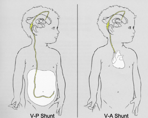
Ventricular ShuntsRadiographic demonstration of skull devices may occur either as an incidental finding or for assessment of the device. In cases where a skull device is imaged radiographically for position/function/calibration, a knowledge of the device, correct patient positioning to demonstrate the device, and the objectives of the examination could be crucial in completing the examination successfully. This page considers all skull prostheses and other implanted cranial devices and the radiographic techniques to demonstrate them.
adapted from <a class="external" href="http://the-callahans.com/susete/shunt.htm" rel="nofollow" target="_blank">http://the-callahans.com/susete/shunt.htm</a>"Hydrocephalus... is a neurological condition in which the ventricular volume of cerebrospinal fluid (CSF) is abnormally large in relation to brain volume. It can be broadly classified as either obstructive, non obstructive or functional and there are various etiologies, including hemorrhage, infection, tumor and congenital anomalies. Hydrocephalus also may be idiopathic.
Though not all patients respond well, many experience measurable clinical improvement from shunting CSF to another location in the body where it can be absorbed, most commonly the peritoneum. The ventriculoperitoneal
(V-P) shunt has, for the most part, replaced the ventriculoatrial (VA) shunt due to the lessened likelihood of infection or clotting. Nevertheless, V-P shunts are subject to complications such as breakage, obstruction and migration or malpositioning of the catheters. An additional concern is proper maintenance of the valve pressure in the shunting device so that over- or underdrainage does not occur. A variety of devices
- flow-controlled” valves, antisiphon devices and programmable shunts- have been introduced because of this concern, but none are completely free of overdrainage complications"
quoted from
A. ROBERT SCHLEIPMAN, M.A., and NANCY OLSEN BAILEY, R.N.,
Programmable Shunt Radiography,
Radiography,
VOLUME 73/NUMBER 2.
The Codman Hakim Shunt
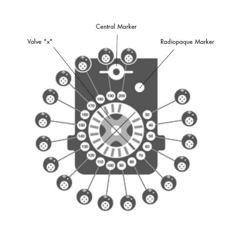
The Codman Hakim shunt is a programmable ventricular shunt valve system used to treat hydrocephalus. With this system, valve pressure can be ascertained easily with plain-film radiographs. (A. ROBERT SCHLEIPMAN, M.A., and NANCY OLSEN BAILEY, R.N., Programmable Shunt Radiography, Radiography, VOLUME 73/NUMBER 2)
Radiographic Technique
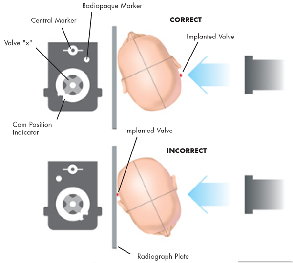
<a class="external" href="http://www.codman.com/binary/org/CODMAN/PDF/VAL-10-001-CHPV-proc-guide.pdf" rel="nofollow" target="_blank">http://www.codman.com/binary/org/CODMAN/PDF/VAL-10-001-CHPV-proc-guide.pdf</a>"A proper radiograph will be generated when the film is shot perpendicular to the plane of the valve with the non-implanted
side of the patient’s head resting on the plate. The film must be taken in relation to the valve and not the patient’s anatomy." <a class="external" href="http://www.codman.com/binary/org/CODMAN/PDF/VAL-10-001-CHPV-proc-guide.pdf" rel="nofollow" target="_blank">http://www.codman.com/binary/org/CODMAN/PDF/VAL-10-001-CHPV-proc-guide.pdf </a>
Accurate positioning of the patient, which depends on valve placement, often deviates from routine projections performed with other ventricular shunts.
It is considered prudent to radiographically check ventricular shunt valves following MR imaging. <a class="external" href="http://cat.inist.fr/?aModele=afficheN&cpsidt=897212" rel="nofollow" target="_blank">MIWA, KONDO, and SAKAI</a> reported the following findings when testing shunt valve susceptibility to MR fields
"In one experiment, two valves were affixed to a human model: one was installed in the right retroauricular region and the other at the anterior chest wall. The pressure was changed in 58 (80.6%) of 72 tests in the valve in the right retroauricular region and in 46 (63.9%) of 72 tests in the valve at the anterior chest wall. In some tests with the valve pressure originally set at 200 mmH2O striking changes to lower pressures were observed. In the other experiment, the changes of pressure settings in seven patients with a shunt system installed were checked before and after random filliping with the tip of an index finger 50 times. In all 7 patients, the pressures initially set were greatly changed, by up to 120 mmH2O of the maximum range." quoted from
K.Miwa1, HiroakiKondo1 and NoboruSakai2Child's Nervous SystemK. Miwa1Pressure changes observed in Codman-Medos programmable valves following magnetic exposure and filliping
Volume 17, Number 3 / February, 2001
<a class="external" href="http://www.codman.com/binary/org/CODMAN/PDF/VAL-10-001-CHPV-proc-guide.pdf" rel="nofollow" target="_blank">http://www.codman.com/binary/org/CODMAN/PDF/VAL-10-001-CHPV-proc-guide.pdf</a>"The setting of the valve can be determined by comparing the position of the radiopaque maker on the valve cam to the fixed position of the radiopaque righthand side indicator on the base plate of the valve." <a class="external" href="http://www.codman.com/binary/org/CODMAN/PDF/VAL-10-001-CHPV-proc-guide.pdf" rel="nofollow" target="_blank">http://www.codman.com/binary/org/CODMAN/PDF/VAL-10-001-CHPV-proc-guide.pdf</a>
Case 1
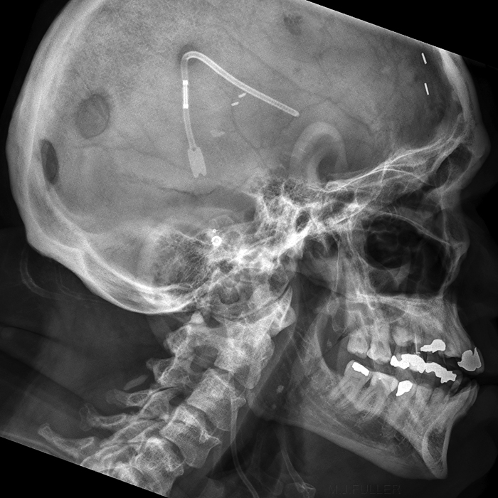
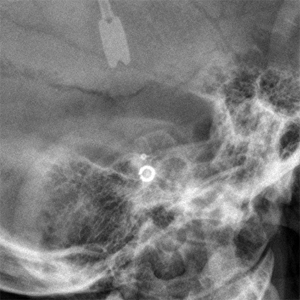
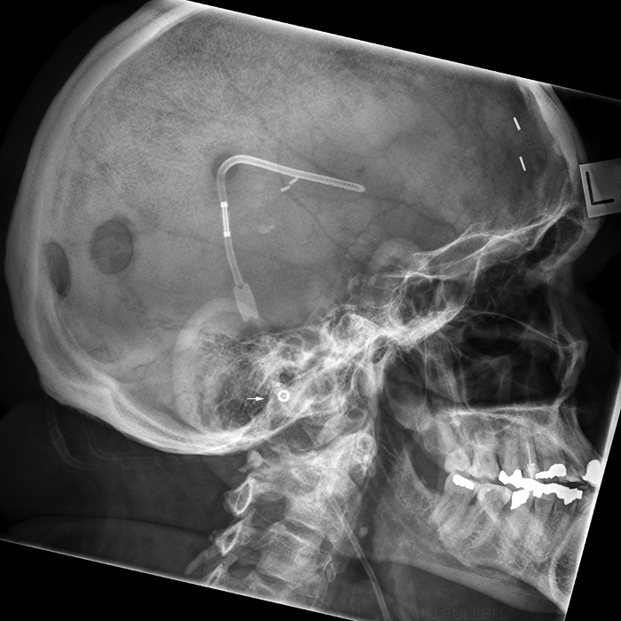
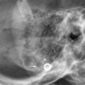
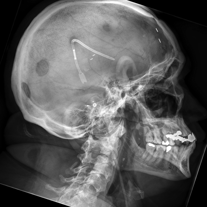
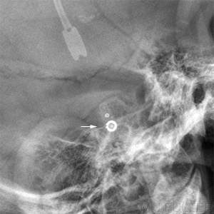
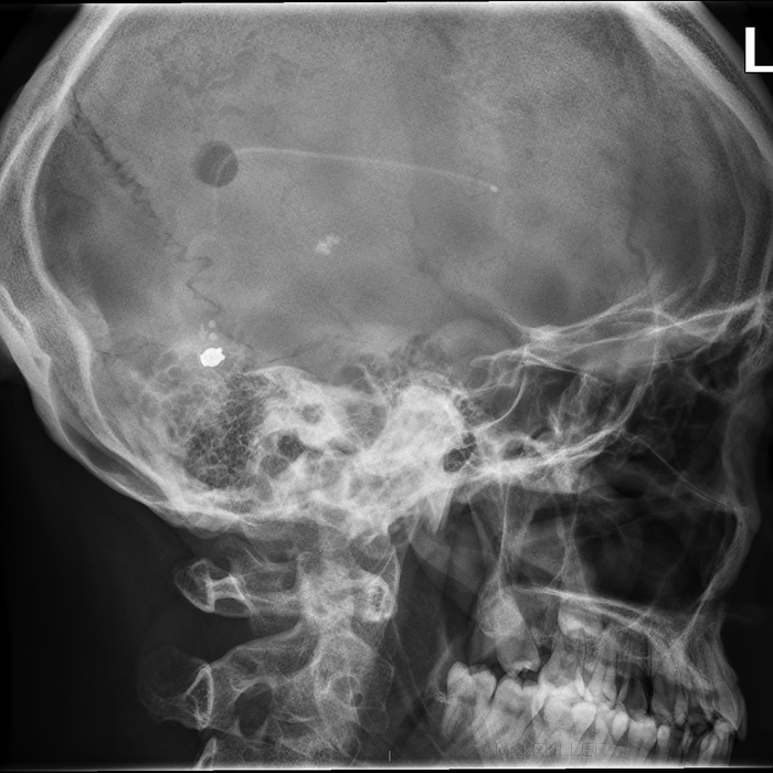
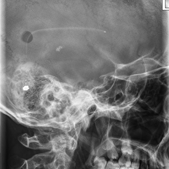
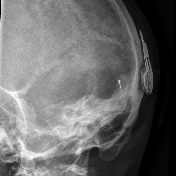
This patient has a Codman Hakim programmable ventricular shunt valve which was imaged a number of times radiographically.
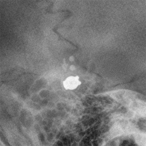
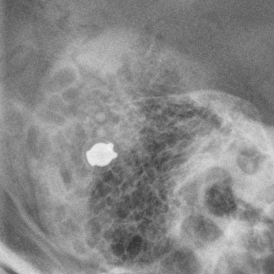
Photographically magnified programmable ventricular shunt. (same image as left)
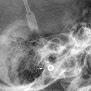
Photographically magnified programmable ventricular shunt. (same image as left)
Burr holes, metallic sutures and pineal calcification noted
Photographically magnified programmable ventricular shunt. (same image as left).
Case 2
Photographically magnified programmable ventricular shunt. (same image as left)
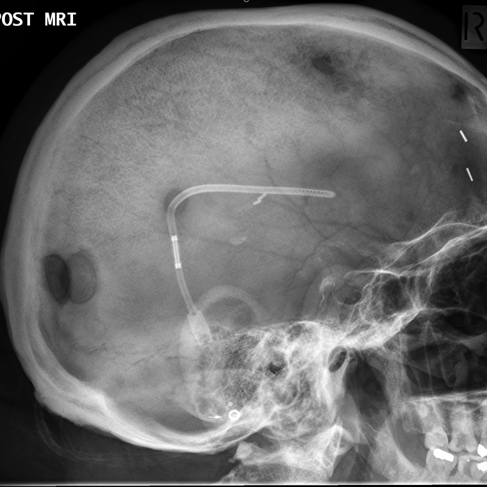
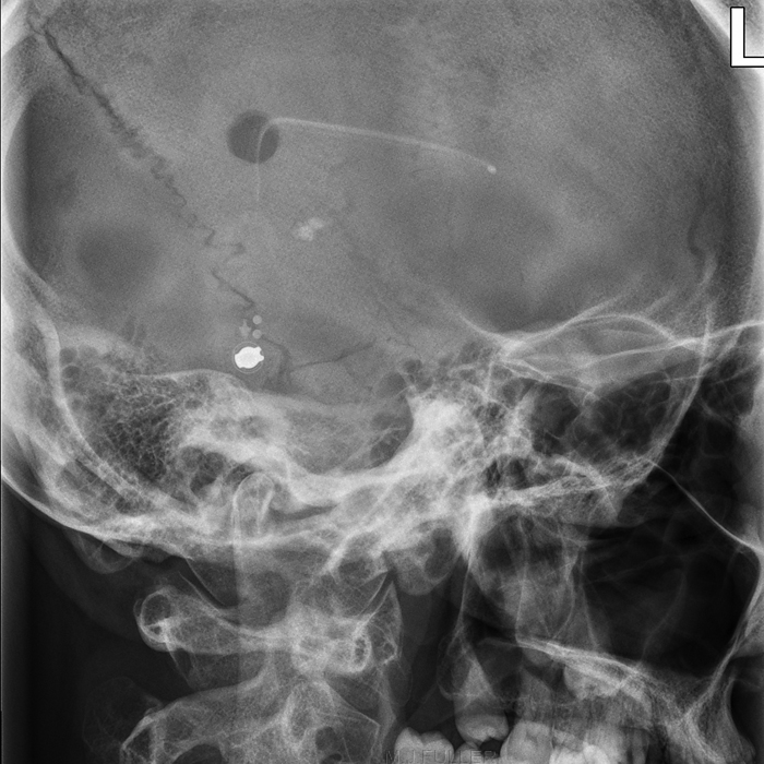
This patient has a ventricular shunt valve which was imaged a number of times radiographically post MRI imaging.
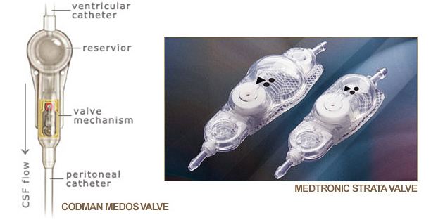
source: <a class="external" href="http://nphsurgery.org/About-Shunt-Systems.html" rel="nofollow" target="_blank">http://nphsurgery.org/About-Shunt-Systems.html</a>This patient has a medtronic (ventricular shunt) strata valve.
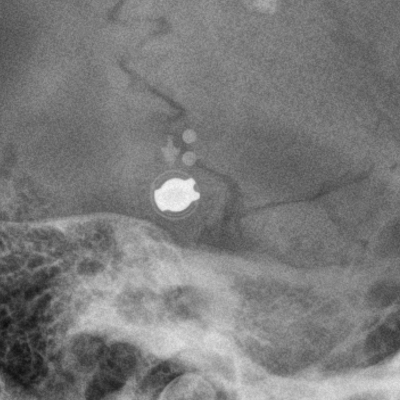
Photographically magnified programmable ventricular shunt. (same image as left)
Photographically magnified programmable ventricular shunt. (same image as left)
Photographically magnified programmable ventricular shunt. (same image as left)
Comment
The demonstration of this programmable shunt radiographically is improved when it is not superimposed over mastoid air cells.
Cochlear Implants
"Cochlear implants are a common and well-accepted method for habilitation of hearing in the profoundly hearing-impaired population... The insertion of the electrode array into the cochlea is often verified with a plain radiograph obtained in the intraoperative or early postoperative period." <a class="external" href="http://www.med.unc.edu/earandhearing/research/pdfs/Prospective_Radiographs.pdf" rel="nofollow" target="_blank">Benjamin J. Copeland, Harold C. Pillsbury, and Craig A. Buchman. Prospective Evaluation of Intraoperative Cochlear Implant Radiographs. Otology & Neurotology 25:295–297, 2004</a>.
The Device
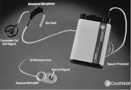
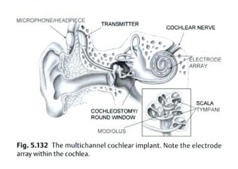
<a class="external" href="http://www.ajnr.org/cgi/reprint/16/7/1517.pdf" rel="nofollow" target="_blank">Barry A. Shpizner et al, Postoperative Imaging of the Multichannel Cochlear Implant, AJNR Am J Neuroradiol 16:1517–1524, August 1995</a>"The multichannel cochlear implant prosthesis consists of both externally worn and surgically implanted components . The externally worn components include the headset and the speech processor. The implanted components include
the receiver/stimulator and the electrode array. The receiver/stimulator is placed beneath the postauricular soft tissues within a well drilled out of the calvarium. The electrode array is inserted into the scala tympani through a cochleostomy, which is drilled into the cochlear promontory approximately 1 mm anterior to the round window"
<a class="external" href="http://www.ajnr.org/cgi/reprint/16/7/1517.pdf" rel="nofollow" target="_blank">Barry A. Shpizner et al, Postoperative Imaging of the Multichannel Cochlear Implant, AJNR Am J Neuroradiol 16:1517–1524, August 1995</a>
Radiography
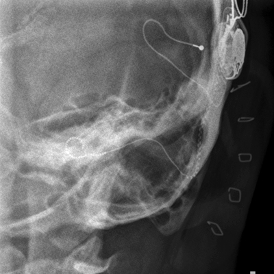
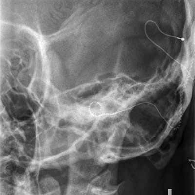
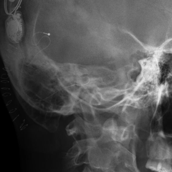
The aim of cochlear implant radiography is to produce a clear undistorted demonstration of the implant in relation to the bony anatomy.
The objective is to achieve the following- exposure and detail allowing demonstration of the individual electrode elements
- clear demonstration and profiling of the superior semicircular canal
source: <a class="external" href="http://journal.shouxi.net/upload/pdf/154/3016/156507_1200.pdf" rel="nofollow" target="_blank">http://journal.shouxi.net/upload/pdf/154/3016/156507_1200.pdf</a>
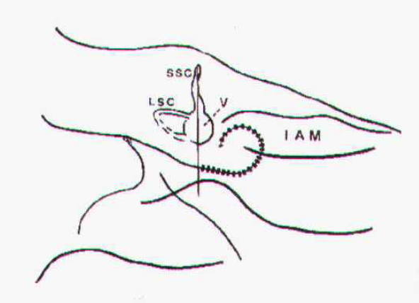
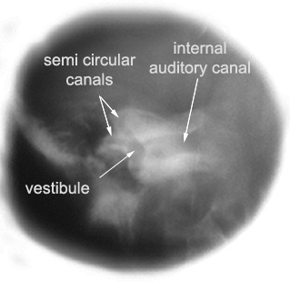
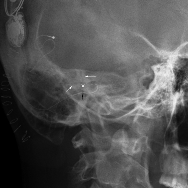
The position of the cochlear implant is shown in relation to the vestibule, superior semicircular canal, lateral semicircular canal, and internal auditory meatus.
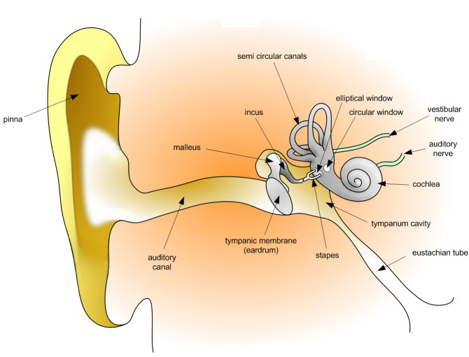
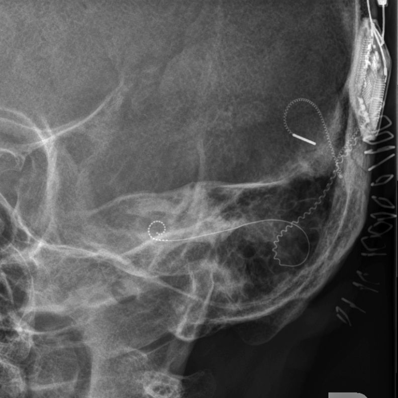
source: <a class="external" href="http://upload.wikimedia.org/wikipedia/commons/7/7c/HumanEar.jpg" rel="nofollow" target="_blank">http://upload.wikimedia.org/wikipedia/commons/7/7c/HumanEar.jpg</a>This image demonstrates the auditory anatomy. This is a DR image produced with a Philips Digital Diagnost (release II). The radiographer utilised a manual exposure technique. This image demonstrates the image quality that can be achieved with a DR system.
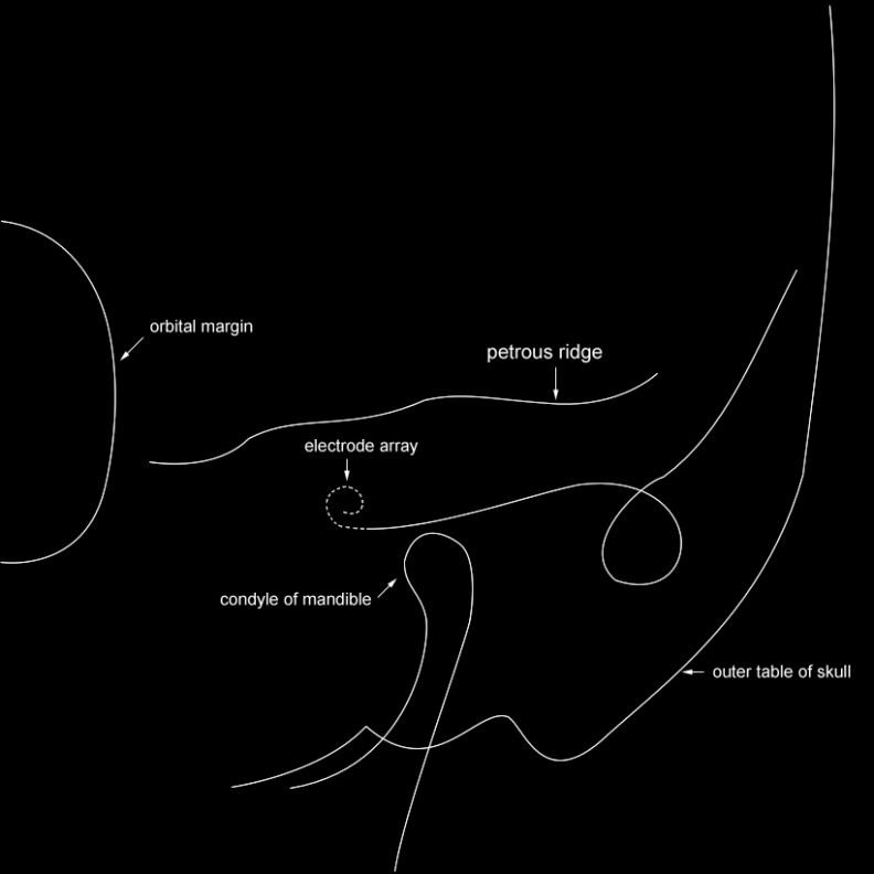
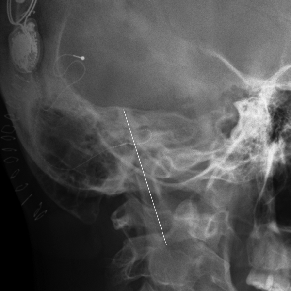
The superior semicircular canal is not well demonstrated possibly due to under-rotation of the patient's skull.The relative positions of the electrode array, orbital margin, and head of mandible are demonstrated in this diagram.
Modified Stenvers for Cochlear Implant
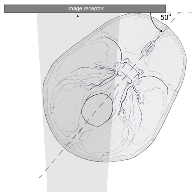
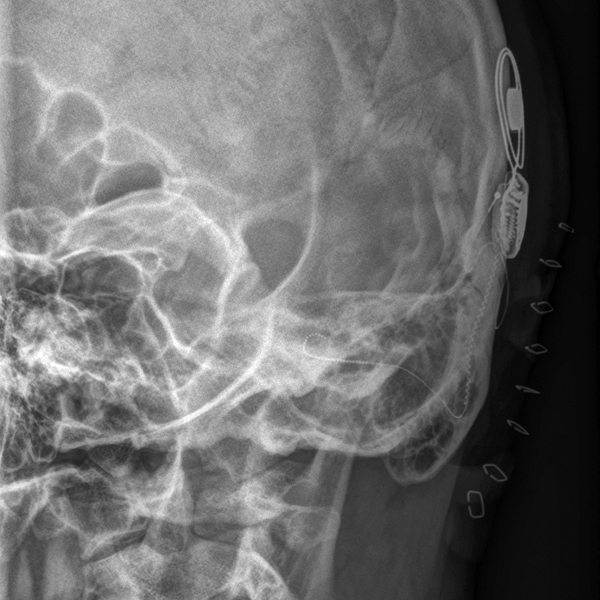
adapted from <a class="external" href="http://www.wfns.org/filebin/images/review_figures/vol5N1_006.jpg" rel="nofollow" target="_blank">http://www.wfns.org/filebin/images/review_figures/vol5N1_006.jpg</a>A request for a "modified Stenver's view will often be made for demonstration of a cochlear implant post operatively. Radiography of the cochlear implant is best performed PA to reduce radiation dose to the patient's orbits. The patient's infraorbito-meatal line (syn. Reid's baseline or Frankfurt line) is positioned at 90 degrees to the IR/cassette. The mid-saggital plane is at 50 degrees to the I.R./cassette. Centre and collimate to include all of the petrous temporal bone on the side of interest.
Whilst mention of the word "Stenvers" might strike fear into the hearts of most radiographers, the technique is essentially very simple to master.
The patient may be required to remain erect for a period immediately post-op necessitating erect radiography during this period.
Xu et al describe the modified Stenver's position for cochlear implant as follows"The patient is sitting in front of a vertical device. First, the head is rested on the forehead, nose and zygomatic bone on the implanted side. Then, the midsaggital plane (M) is adjusted to form an angle of 90 degrees with the plane of the film (F) by using a protractor as a guide and the flexion of the neck is adjusted to make the infraorbital plane (IOP) perpendicular to the film. A fine-focus tube and small localising cone are essential. The central ray (CR) is directed to exit the skull at a point which is 3.0cm anterior and 2.0cm superior to the external auditory meatus at a right angle to the film."
Quoted from
J Xu, S A Xu, M A Marsh and G M Clarke
Post-operative Radiological Examination of Multichannel Intracochlear Electrode Array
The authors recommend a non-grid technique- this would reduce patient radiation dose, particularly to the orbits, but would need to be balanced against the need for adequate contrast resolution to achieve demonstration of the electrode array elements.
Counting Electrodes
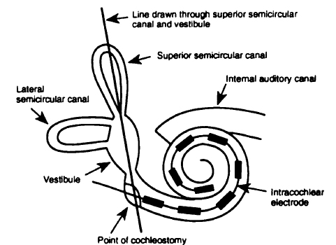
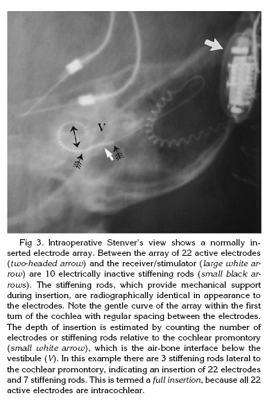
It is important for the radiographer to recognise that the successful surgical positioning of the cochlear implant is established by counting the number of electrodes in the array past the point of cochleostomy on plain film imaging. An inadequately penetrated image may not provide enough detail to count individual electrode elements.
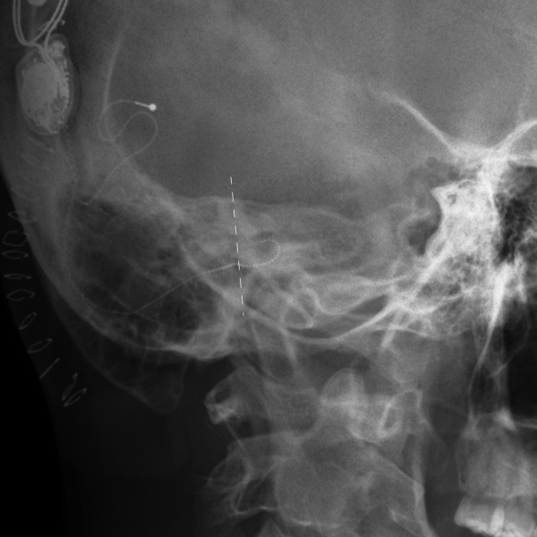
<a class="external" href="http://www.ajnr.org/cgi/reprint/16/7/1517.pdf" rel="nofollow" target="_blank">Source: Barry A. Shpizner et al, Postoperative Imaging of the Multichannel Cochlear Implant, AJNR Am J Neuroradiol 16:1517–1524, August 1995</a>The point of cochleostomy is determined by projecting a line drawn through the SSC and the vestibule on the radiographs. The position of the cochlear implant is assessed in relation to this line.
Exposure Technique
Image Analysis
Examples
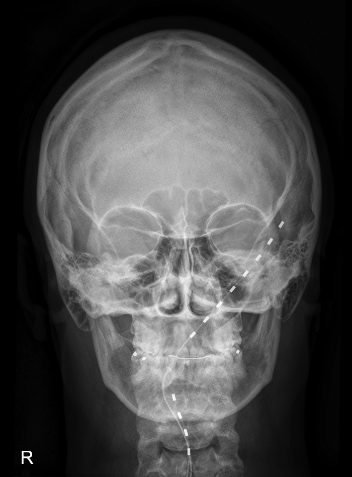
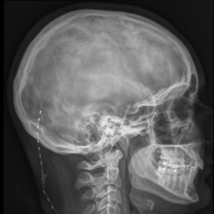
Occipital Nerve StimulatorComment
The most common failing seen in cases reviewed by the author was underexposure. A manual setting of exposure factors should overcome this failing. The position of the orbit and the mandibular neck line can be useful guides for image analysis.
Some patients with chronic migraine headache respond well to a device known as an occipital nerve stimulator. "Occipital nerve stimulation (ONS) involves implanting an electronic device and small wires under the skin at the back of the neck near the occipital nerves. A battery to power the device is also surgically implanted in the patient's body, usually in the abdomen or buttock. The device sends electrical impulses through the wires to the occipital nerves at the base of the head to interrupt pain signals." <a class="external" href="http://somebodyhealme.dianalee.net/2008/06/ahs-meeting-news-occipital-nerve.html" rel="nofollow" target="_blank">http://somebodyhealme.dianalee.net/2008/06/ahs-meeting-news-occipital-nerve.html</a>
Radiography
... back to the Wikiradiography home page
...back to the Applied Radiography home page
