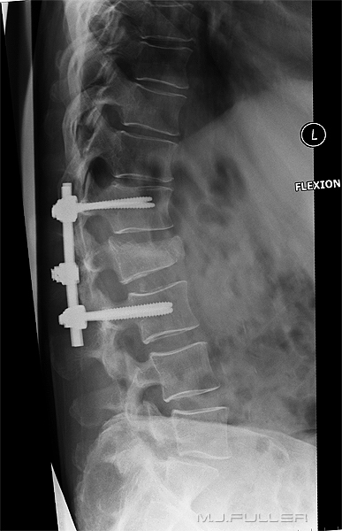
Lateral Lumbar Spine Radiography
The status of plain film radiography of the lumbar spine has changed in recent years. There is greater awareness of the relatively high radiation dose to the patient, the limitations of the plain film examination and the alternate imaging modalities. It is the responsibility of the radiographer to be aware of current best practice and to play the role of gate-keeper where appropriate. In spite of the limitations of plain film radiography of the lumbar spine, patients are still referred for plain film lumbar spine X-ray examinations, particularly in a trauma setting, and the radiographer has a duty to produce images of the highest quality.
Radiation Protection
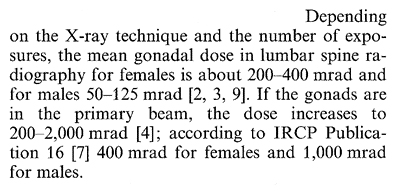
The radiation dose to the patient associated with a routine lumbar spine X-ray examination is relatively high compared with other plain film X-ray examinations. It is the duty of the radiographer to minimise the radiation dose to the patient. The lumbar spine X-ray examination is one of the examinations that you could reasonably refuse to perform in cases of inappropriate indications on the basis of duty of care to the patient. A plain film X-ray examination of a woman of childbearing age, who is likely to be suffering from muscular pain, is below an acceptable standard of care. Seek the advice of a senior colleague if you consider that a lumbar spine X-ray examination referral is inappropriate. If you are the senior colleague, discuss the referral with the referring doctor to establish whether there are exceptional circumstances. If your institution has clinical pathways for back pain investigation, establish with the referring doctor if the case is within the guidelines. No female of child-bearing age should undergo lumbar spine radiography until their pregnancy status is clearly established.
A urine beta-HCG test should be undertaken prior to imaging if there is any change that the patient may be pregnant.
- If you are not pregnant, the test is negative
- If you are pregnant, the test is positive
<a class="external" href="http://www.springerlink.com/content/v1834533k2388140/" rel="nofollow" target="_blank">Skeletal Radiology</a>
<a class="external" href="http://www.springerlink.com/content/v1834533k2388140/" rel="nofollow" target="_blank">AimoMoilanen1 , Marja-LiisaKokko1 and MaunuPitkänen</a><a class="external" href="http://www.springerlink.com/content/v1834533k2388140/" rel="nofollow" target="_blank">Gonadal dose reduction in lumbar spine radiography </a>
<a class="external" href="http://www.springerlink.com/content/v1834533k2388140/" rel="nofollow" target="_blank">Issue Volume 9, Number 3 / February, 1983</a>
<a class="external" href="http://www.springerlink.com/content/v1834533k2388140/" rel="nofollow" target="_blank">December 10, 2004</a>
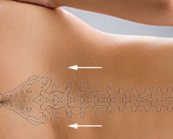
The Finger Width Centring Technique
Adjusting the FFD/SID to suit the Patient Body Habitus
There is a tendency for the intervertebral disc spaces to be demonstrated best at the centre of the image and worst at the periphery of the image (see left). The reason for this phenomenon is that the central intravertebral disc(s) tend to be imaged in true profile while the divergence of the X-ray beam tends to not meet the peripheral lumbar vertebrae at right angles. This might appear to be unavoidable, but much can be done in terms of radiographic technique to overcome this problem.
The chiropractors largely avoid this problem by performing all spine radiography with the patient erect at 180cms. This is not always possible (e.g. trauma patients) requiring an alternate approach.
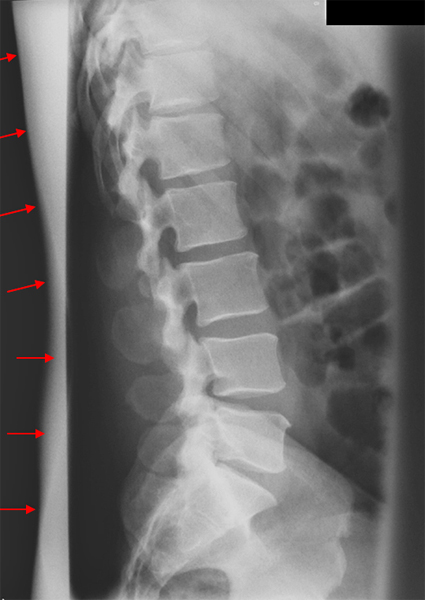
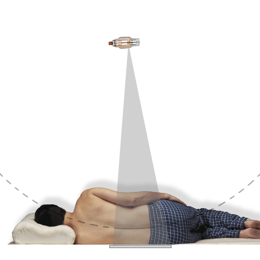
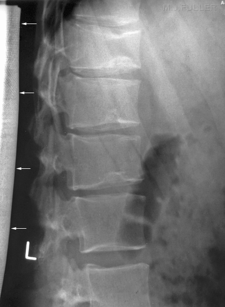
<a class="external" href="http://www.made-in-china.com/image/2f0j00JCPTQLuWghqBM/X-Ray-Tube-CT-18-X762-.jpg" rel="nofollow" target="_blank">and http://www.made-in-china.com/image/2f0j00JCPTQLuWghqBM/X-Ray-Tube-CT-18-X762-.jpg</a>note- this image has been used for illustrative purposes and does not represent a radiographic lateral lumbar spine position.When performing lateral lumbar spine radiography using the table bucky/IR, the patient should be positioned in the rolled lateral position and a careful assessment of the shape of the patient's lumbar spine should be made in this position. You are aiming to set the FFD/SID to a distance where the lumbar spine describes the arc of a circle centred at the focal spot.
I have heard of a radiographer who used a piece of string attached at the level of the focal spot of the X-ray tube and a pencil at the level of the patient's spine and moved the pencil though an arc to ensure that every spinous process was aligned with the arc of a circle centred at the focal spot. This is an extreme technique but, nevertheless, illustrates the principle.
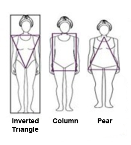
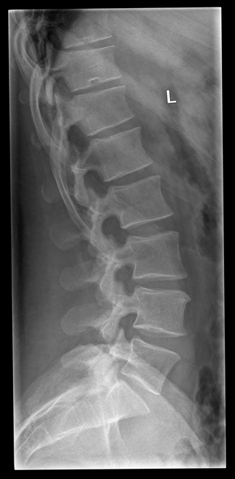
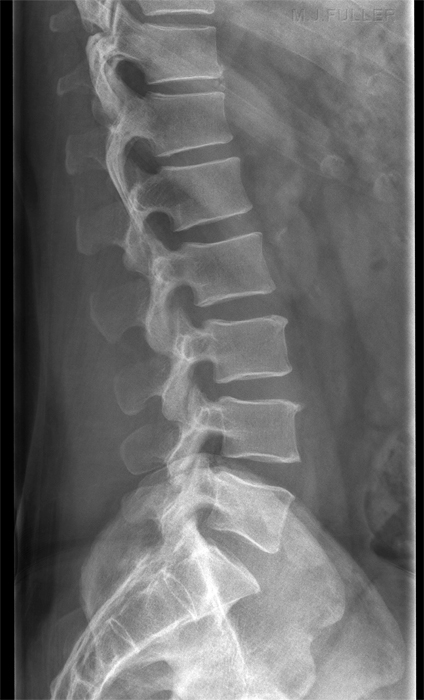
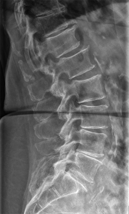
If you are successful, you should produce an image like this (note that this image is collimated to include the thoraco-lumbar junction) The patient's body shape will provide significant clues as to the likely shape of the patient's lumbar spine in the rolled lateral position.
Successful FFD/SID Determination
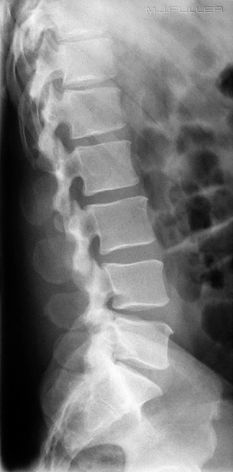
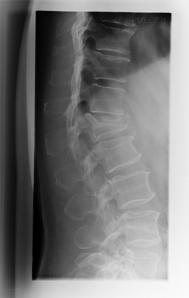
Successful assessment of the curve of the patient's lumbar spine when combined with the other techniques described on this page can result in a lateral lumbar spine image that is both diagnostically adequate and aesthetically pleasing as shown below.
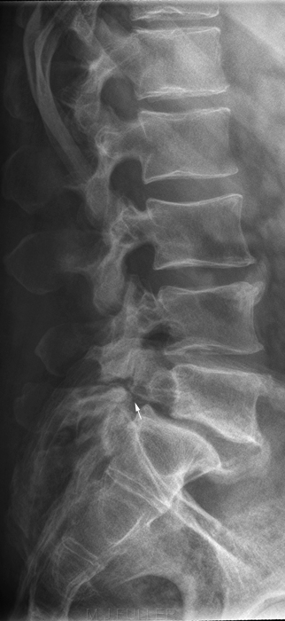
L5 Pars defects noted
Assess the AP view Before Performing the Lateral View
Limiting Scatter Radiation- X-ray Beam Collimation
Limiting Scatter Radiation- Round Cone
The reduction in radiation dose to the patient is possibly greater than would be suggested by this image. It should be remembered that it is not an area of tissue that is saved from irradiation, it is a volume- the X-ray image is two dimensional, but the irradiated tissue is three dimensional.
Limiting Scatter Radiation- Lead Rubber
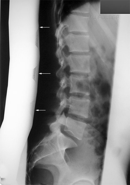
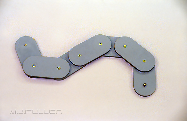
Limiting Scatter Radiation- "Snake"
Aluminium Filter Technique
Exposure technique
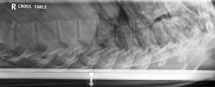
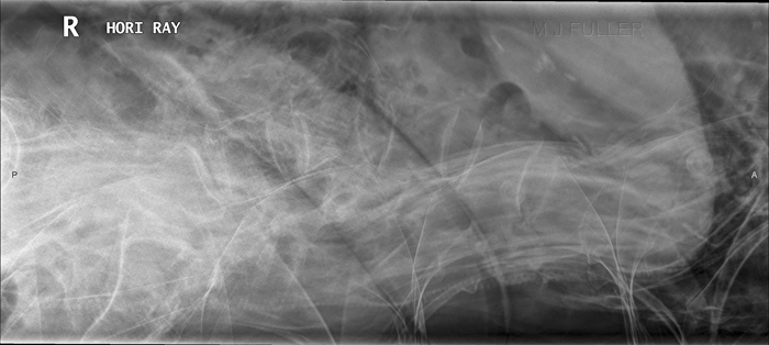
Horizontal Ray Lateral Lumbar Spine TechniqueThe breathing exposure technique is usually associated with lateral thoracic spine radiography. The same technique can be employed for all torso spine plain film imaging.
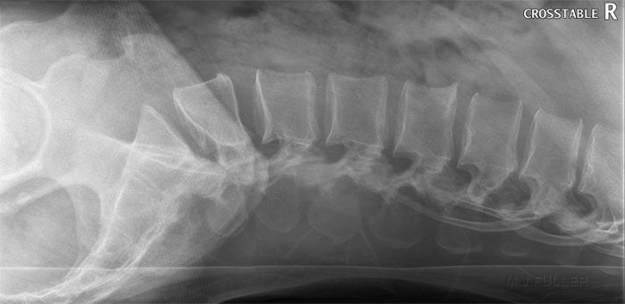
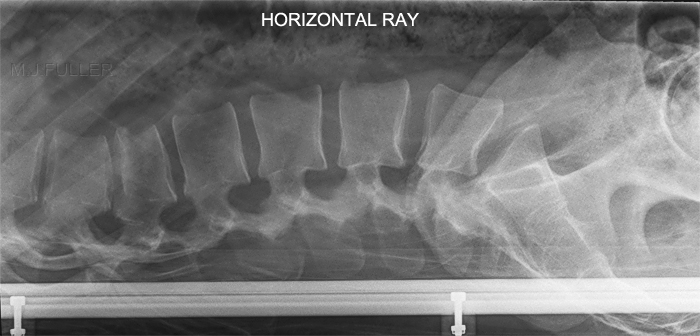
The horizontal ray lateral technique is commonly employed in patients who are unable to roll into the lateral position and/or in patients who have a possibility of an unstable spinal injury.
Thoraco-lumbar Spine- What does this term Imply?
When a patient is referred for radiography of the thoraco-lumbar spine, the inference is that imaging is required of the thoraco-lumbar junction. The vertebra that the referring doctor requires to be imaged may only be known to the referring doctor! The radiographer is sometimes required to make a reasoned judgement as to the intention of the referring doctor. This may range between a requirement for imaging of a known fracture (e.g. t12, L1) or the doctor's intention may be for imaging of considerably more of the thoracic and lumbar vertebrae (in which case the wrong examination was ordered). Speak to the patient about their history and, if still unsure, speak to the referring doctor.
Lateral Lumbosacral Junction Technique
How do you know if it's Lateral?
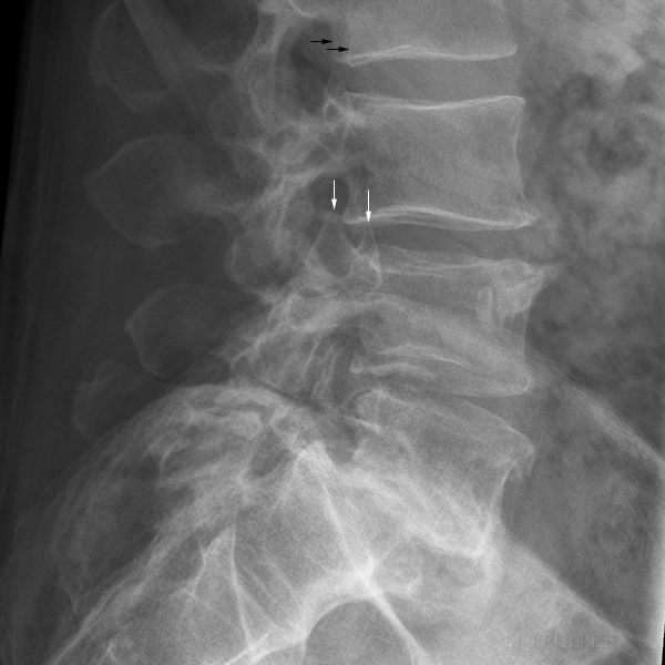
An off-lateral lumbar spine can be identified by one of a number of signs:
- The twin peaks (white arrows) are the superior articulating processes of the vertebra. If the lateral lumbar spine is in a true lateral position, the superior articulating processes will be superimposed.
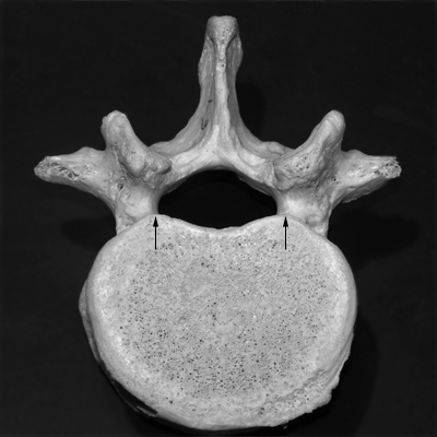
- The black arrows identify the postero-lateral aspects of the vertebral body (see below). They will similarly be superimposed when the patient is positioned in a true lateral position.
<a class="external" href="http://biology.clc.uc.edu/Fankhauser/Labs/Anatomy_&_Physiology/A&P201/Skeletal/selected_bones/lumbar_vertebra_PB050105.JPG" rel="nofollow" target="_blank">http://biology.clc.uc.edu/Fankhauser/Labs/Anatomy_&_Physiology/A&P201/Skeletal/selected_bones/lumbar_vertebra_PB050105.JPG</a>
The Off-lateral Trap
Case 1
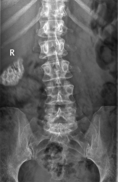
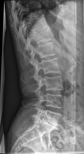
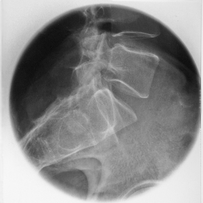
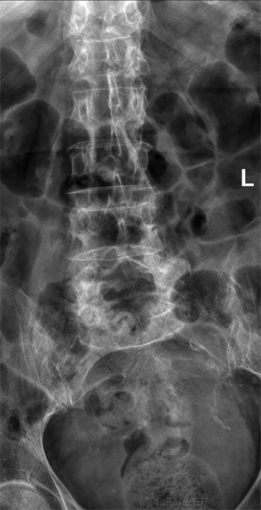
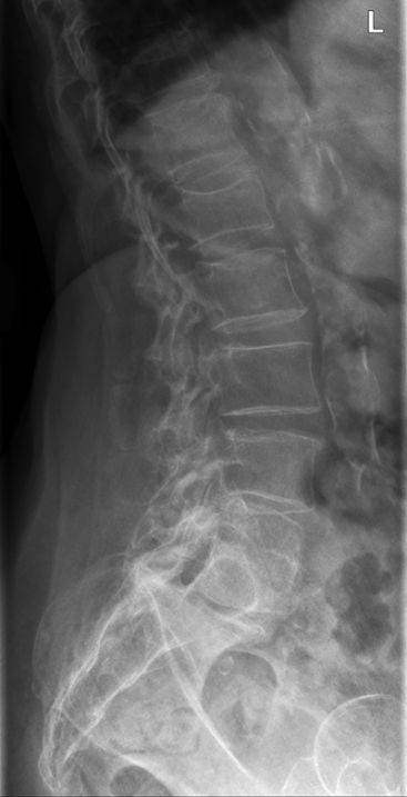
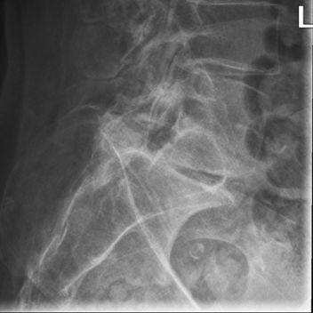
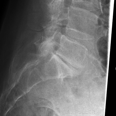
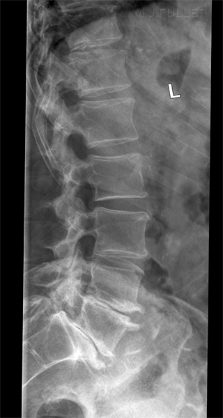
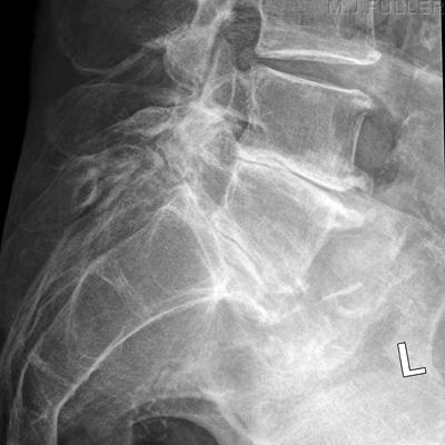
AP Lumbar Spine Lateral Lumbar Spine This elderly lady presented to the Emergency Department with back pain following a fall. The AP lumbar spine image demonstrates no acute abnormality. The lateral lumbar spine image suggests a spondylolisthesis at L5S1 The coned lateral L5S1 image similarly suggests a spondylolisthesis at L5S1
Comment
The reporting Radiologists suspected that the apparent spondylolisthesis may be positional and requested a repeat lateral L5S1 view.
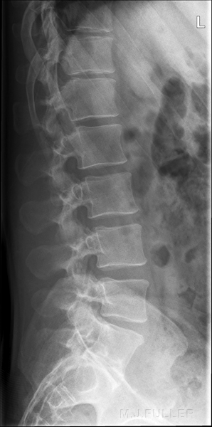
Repeat Lateral Lumbo-sacral Junction The repeat lateral L5S1 image confirms the radiologist's suspicion that the apparent spondylolisthesis at L5S1 was positional/projectional rather than a true pathology. This case demonstrates the need for diligence in ensuring that patients are in a true lateral position when performing lateral lumbar spine radiography.
Case 2
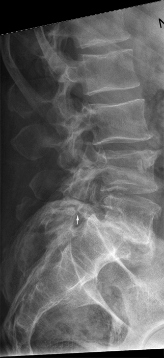
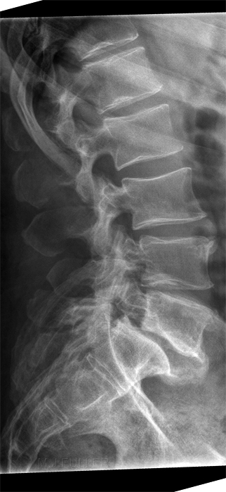
Image 2. Better Lateral Position Image 3. Best Lateral Position This patient has had neutral, flexion and extension lateral lumbar spine radiography. He has a grade 2 spondylolisthesis and bilateral pars interarticularis defects (arrowed). The patient is rotated off true lateral and the demonstration of the L5S1 disc space is poor. This is an acceptable lateral L5S1 position but the lower facet joints are not superimposed. This is a very good lateral position. Note the clarity of demonstration of the bony anatomy and the clear demonstration of the pars interarticularis defects. Compare the demonstration of the bony anatomy and pathology with the first two images.
Compare the L4/5 disc space as demonstrated on the 3 images- this level provides a good illustration of how a good lateral position can provide an appreciation of a joint space and a poor position provides limited information.
This patient has had neutral, flexion and extension lateral lumbar spine radiography. He has a grade 2 spondylolisthesis and bilateral pars interarticularis defects (arrowed). The patient is rotated off true lateral and the demonstration of the L5S1 disc space is poor. This is an acceptable lateral L5S1 position but the lower facet joints are not superimposed.
Transitional Vertebra (Lumbarisations and Sacralisations)
<a class="external" href="http://www.asbweb.org/conferences/1990s/1998/9/figure3.jpg" rel="nofollow" target="_blank">
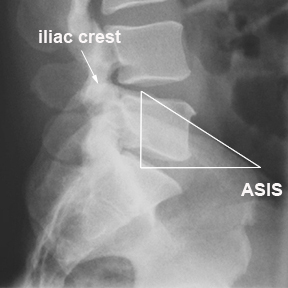
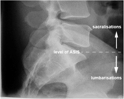
</a>There can be transitional vertebrae throughout the spinal column at the transition levels (i.e. cervico-thoracic, thoraco-lumbar, lumbosacral). For example, the seventh cervical vertebra can have an associated rib (cervical rib) affording it characteristics of a thoracic vertebra. There can be a 13th rib which will suggest the first lumbar vertebra has some thoracic spine characteristics. Some patients will demonstrate absence of the 12th ribs. It can be very difficult for the reporting radiologist to decide what to call a transitional vertebra- is it a lumbar vertebra with some sacral characteristics or is it a sacral vertebra with some lumbar characteristics? Where this can become a problem for the radiographer is in deciding whether you correctly performed a coned lateral L5S1 view when the first sacral vertebral has characteristics of L5.
As a guide, you could consider L5S1 to be at the level of the ASIS and transitional vertebra above this level to be sacralised lumbar vertrebra and vertebra below this level to be lumbarised sacral vertebra. Note that this is a guide only, and consideration should be given to the number of lumbar-like vertebra visible and the position of the 12th ribs.
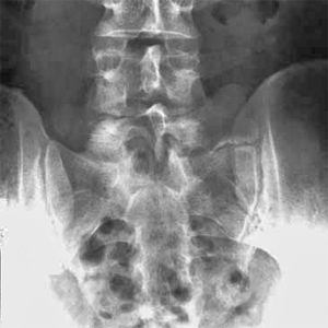
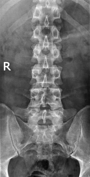
When viewing the AP projection of the lumbar spine, note that the transverse processes of L4 are often orientated slightly cephalad- this can be a useful landmark in identifying lumbar levels.
<a class="external" href="http://www.mypacs.net/cgi-bin/repos/mpv3_repo/wrm/repo-view.pl?cx_subject=3875227&cx_prefsize=medium&cx_from_folder=&cx_repo=mpv4_repo" rel="nofollow" target="_blank">adapted from Alex Maclennan</a><a class="external" href="http://www.mypacs.net/cgi-bin/repos/mpv3_repo/wrm/repo-view.pl?cx_subject=3875227&cx_prefsize=medium&cx_from_folder=&cx_repo=mpv4_repo" rel="nofollow" target="_blank">, Radiologist, Royal Alexandra Hospital, Paisley, United Kingdom
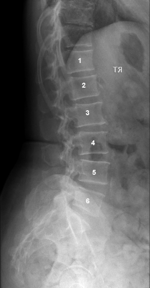
http://www.mypacs.net</a>This is one of those confusing transitional vertebra cases that defies a clear categorisation (left). There are 6 vertebra that demonstrate lumbar characteristics. The verterbra above the vertrebra annotated with "1" has associated ribs. Are these the 12th ribs or are these the 11th ribs with congenital absence of the 12th ribs?
Radiography of the thoracic vertebra to clarify the nature of lumbar transitional vertebra is not warranted unless this will change the management of the patient (unlikely)Schematic presentation of the classification of
Lumbosacral Transitional Vertebrae according to Castellvi.
Type IV is not reproduced : it is
a mixture of type II and III.adapted from <a class="external" href="http://www.actaorthopaedica.be/acta/download/2007-6/01-Bron+et+al.pdf" rel="nofollow" target="_blank">Johannes L. BRON, Barend J. VAN ROYEN, Paul I. J. M. WUISMAN
The clinical significance of lumbosacral transitional anomalies
Acta Orthop. Belg., 2007, 73, 687-695</a>
adapted from <a class="external" href="http://www.actaorthopaedica.be/acta/download/2007-6/01-Bron+et+al.pdf" rel="nofollow" target="_blank">Johannes L. BRON, Barend J. VAN ROYEN, Paul I. J. M. WUISMAN
The clinical significance of lumbosacral transitional anomalies
Acta Orthop. Belg., 2007, 73, 687-695</a>
Unliateral transitional features on left
Castellvi has classified the lumbosacral transitional vertebrae as shown left.
Transitional Vertebrae Examples
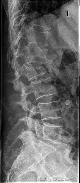
This lateral lumbar spine image demonstrates 5 lumbar-like vertebrae below T12 (identified by associated ribs). This may not be a case of transitional vertabra. The L5 vertebra is however sited at a level that you would expect to see S1. Lateral L5S1 of same patient. Evidence of advanced degeneration of the lower 2 lumbar intervertebral discs and spondylolisthesis at L5S1. ? pars defects at L5.
The first sacral vertebra has some lumbar characteristics.
The Ring Apophysis
<a class="external" href="http://www.asbweb.org/conferences/1990s/1998/9/figure3.jpg" rel="nofollow" target="_blank">V.R. Yingling1, S.M. McGill2
THE RESPONSE OF THE INTERVERTEBRAL DISC, THE PARS INTERARTICULARIS AND THE POSTERIOR LIGAMENTS TO EXTERNAL ANTERIOR SHEAR LOADING </a>Outside of the true epiphyseal plates (of the vertebral body), a cartilaginous ring apophysis develops on the outer rings of the vertebral bodies. The ring apophysis does not contribute to the longitudinal growth of the vertebral body. By age 14 the ring apophysis begins to ossify, eventually fusing with the vertebral body by age 18. This appearance should not be confused with pathological appearance.
[apophysis&source=bl&ots=QvDMlgX_tN&sig=kUHJ0pVXC1iZnkwHJ3qFulHse1g&hl=en&ei=ImeDSt2zG9KSkQXK3Oi8BA&sa=X&oi=book_result&ct=result&resnum=13#v=onepage&q=ring apophysis&f=false|Daniel Kim, Randal Betz, Stephen Huhn, and Peter Newton, Surgery of the Pediatric Spine, 2008, p9]
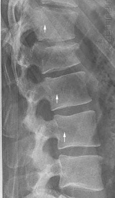
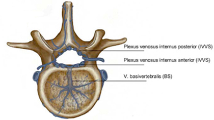
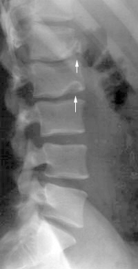
Venous Impression of the Basivertebral Veins
<a class="external" href="http://www.springerlink.com/content/g718n3652w216626/" rel="nofollow" target="_blank">SilkeBecker and BronekBoszczyk, Balloon Kyphoplasty, 2008</a>The arrowed structures are the ostia of the basivertebral veins
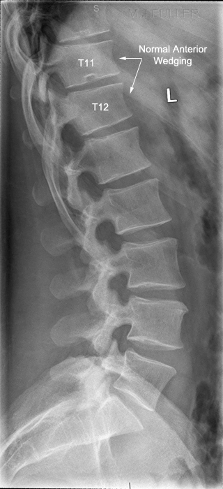
How Much Wedging is normal?
| "Vertebral body height: In the normal spine from T11 to L2, the vertebral segments are typically wedge-shaped anatomically. This normal appearance will present with approximately 10 percent to 15 percent or 1-3 mm less anterior body height compared to posterior body height. A common pitfall related to this is when normal morphology is confused with compression deformity. Loss of height at the anterior aspect of the vertebral body is the most common radiographic finding for compression fractures.Typically, disc material will remain intact and there will be no apparent loss of intervertebral disc height.In older, healed compression deformities, there is typically anterior wedge deformity greater than 15 percent. Some authors have stated that the degree of loss of height must exceed 30 percent to be detected on plain film." | ||
| <a class="external" href="http://www.dynamicchiropractic.ca/mpacms/dc_ca/article.php?id=51049" rel="nofollow" target="_blank">http://www.dynamicchiropractic.ca/mpacms/dc_ca/article.php?id=51049</a> |
This is a normal lateral lumbar spine (except for pars defects at L5). Note the normal slight anterior wedging of the vertebral bodies at T11 and T12.
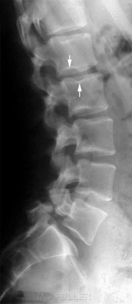
Schmorl's Nodes
Limbus Vertebrae
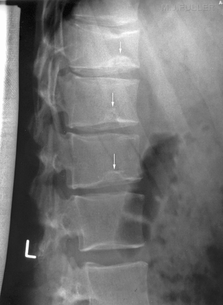
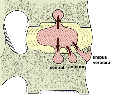
A limbus vertebra is closely related to a Schmorl node"
<a class="external" href="http://radiopaedia.org/articles/schmorl_nodes" rel="nofollow" target="_blank"> Behrang Amini, MD/PhD</a>
adapted from <a class="external" href="http://www.emedmag.com/html/pre/xray/xray/1204.asp" rel="nofollow" target="_blank">Theodore E. Keats, MD in http://www.emedmag.com/html/pre/xray/xray/1204.asp</a>
"The anterior defect of L1 in this patient is a limbus vertebra, and that of L2 is a classic Schmorl's node. The limbus vertebra is the result of anterior protrusion of the intervertebral disk beneath the ring apophysis of the growing vertebral body, which prevents union of the two structures. The Schmorl's node is the product of intrabody herniation of the nucleus pulposus."<a class="external" href="http://www.emedmag.com/html/pre/xray/xray/1204.asp" rel="nofollow" target="_blank">Theodore E. Keats, MD in http://www.emedmag.com/html/pre/xray/xray/1204.asp</a><a class="external" href="http://www.burtonreport.com/infspine/Genomic+Anatomy+of+Spine+Disorders.htm" rel="nofollow" target="_blank">adapted from Ghosh P: The Biology of the Intervertebral Disc, Vol. I, </a>
<a class="external" href="http://www.burtonreport.com/infspine/Genomic+Anatomy+of+Spine+Disorders.htm" rel="nofollow" target="_blank"> CRC Press, 1988 in The Burton Report</a>
<a class="external" href="http://www.burtonreport.com/infspine/Genomic+Anatomy+of+Spine+Disorders.htm" rel="nofollow" target="_blank">http://www.burtonreport.com/infspine/Genomic%20Anatomy%20of%20Spine%20Disorders.htm</a>
Case 1
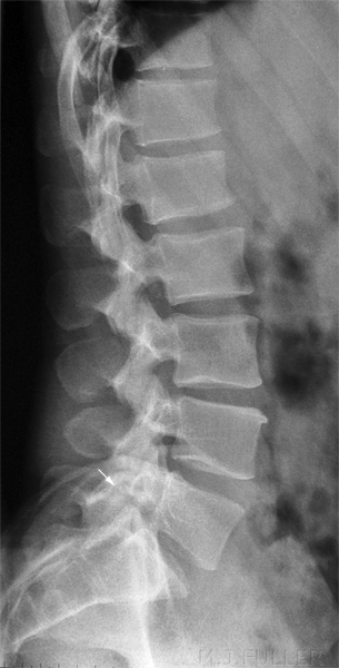
This 20 year old female patient presented to the Emergency Department with low back pain. The patient had a history of involvement in a motor vehicle accident (MVA) 24 hours prior.
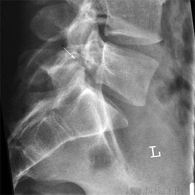
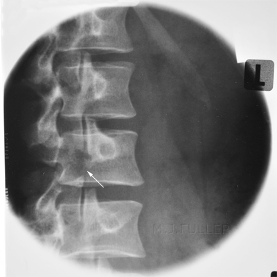
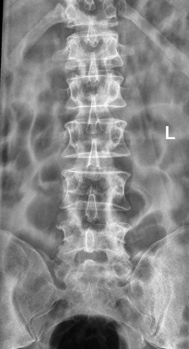
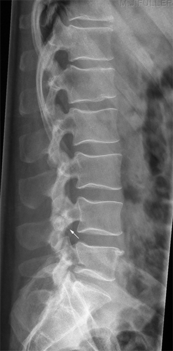
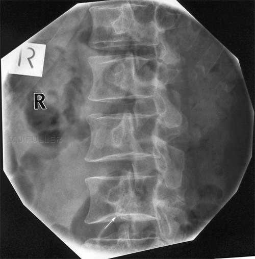
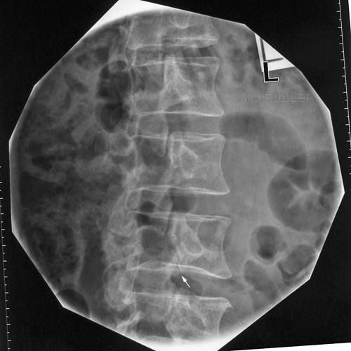
This is an AP lumbar spine image taken with a long exposure time using a film/screen technique. This is a lateral lumbar spine using a long exposure time and long ffd on film/screen . In addition, an aluminium wedge filter has been placed to reduce the exposure to all but L5 and lower. There is a defect of the L5 pars interarticularis- probably bilateral (white arrow). The coned lateral L5S1 image supports the diagnosis of a L5 pars interarticularis defect.
Elastic artifact noted
Comment
The referring doctor reviewed the images and referred the patient for CT lumbar spine imaging in lieu of obliques of the lower lumbar spine. The pars defects were shown to be well corticated suggesting that they were old/congenital.
Case 2
This 24 year old female patient presented to the Emergency Department following acute onset of low back pain. The patient has a history of involvement in a motor vehicle accident (MVA) 5 years ago.
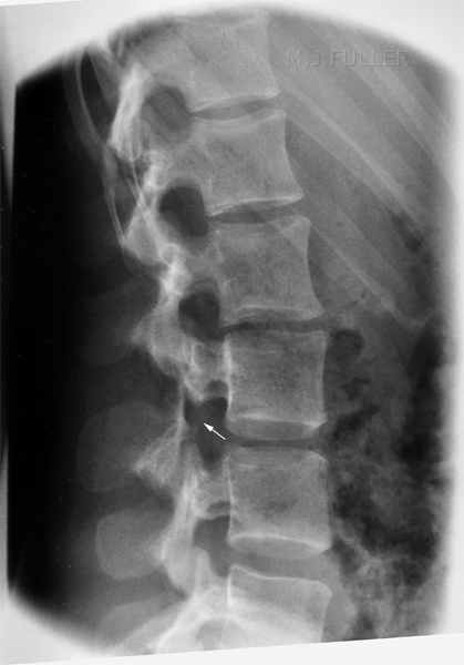
The lateral lumbar spine demonstrates pars interarticularis defects at L3 (film/screen technique circa 1997) The coned LPO oblique view demonstrates a pars interarticularis defect on the right Similarly, the left oblique demonstrates a pars interarticularis defect.
Comment
The pars defects in this case were considered to be non-acute.
Case 3
This 46 year old male presented to the Emergency Department with back pain following lifting a heavy object. He was referred for radiography of the lumbar spine.
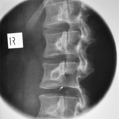
This is an AP lumbar spine image taken with a breathing long exposure time using a CR technique. There is no obvious abnormality demonstrated. This is a CR lateral lumbar spine image using a long exposure time and long SID with breathing technique. There is some loss of vertebral body height anteriorly at L1. There is also a suggestion of loss of vertebral body height posteriorly at L5. A defect in the pars interarticularis is seen at L4 with increased sclerosis and a lucent line (arrowed). The pars defects were noted by the radiographer who proceeded to perform oblique views of the area of interest. There is abnormal irregular bone growth associated with the right pars interarticularis and a lucent corticated defect suggesting an old fracture (arrowed). There is a lucent defect with corticated margins in the left pars interarticularis (arrowed) suggesting an old injury.
Case 4
This patient was referred on multiple occasions for follow-up imaging of a L1 crush fracture.
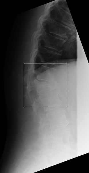
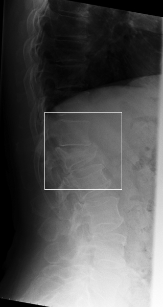
This is a lateral thoracolumbar spine position. The AEC devise was selected resulting in slight underexposure for the area of interest (L1). This is caused by the lungfields partially overlying the centre AEC chamber. The image is degraded by scatter radiation associated with failure to collimate adequately. The exposure was made on inspiration. Similar projection on expiration. The AEC has achieved a better result on expiration. The image is degraded (low contrast) associated with scatter radiation. The exposure was made on expiration. The radiographer has selected a manual exposure with an exposure time of 1.6 seconds. The breathing technique has resulted in blurring (movement unsharpness) of the soft tissues and associated improved visualisation of the L1 fracture. The radiographer has partially collimated within the patient's skinline resulting in a reduction in scatter radiation and associated increased contrast.
...back to the Applied Radiography home page
