Imaging Vertebral Body Wedge Fractures
Introduction
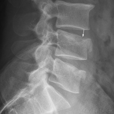
Mechanisms of InjuryWedge fractures of the thoracic and lumbar spine are commonly seen by radiographers. This page considers all aspects of wedge fractures including radiographic techniques for demonstrating them and plain film and CT pathological appearances of wedge fractures
An wedge fracture is usually caused by an axial load and/or hyperflexion. Osteoporotic patients are particularly vulnerable to wedge fractures of the thoracic and lumbar spine which may be caused by relatively minor forces. "The inherent fixed thoracic kyphosis automatically transforms an axial loading force into the equivalent of a flexing mechanism of injury" (John H. Harris et al, The Radiology of Emergency Medicine, 3rd Ed, 1993, p 246, Williams and Wilkins).
Satisfaction Syndrome
It is not uncommon for multiple wedge fractures to result from a single injury. If a wedge fracture is demonstrated, it is prudent to consider whether there may be more wedge fractures that you have not demonstrated.
Exposure technique
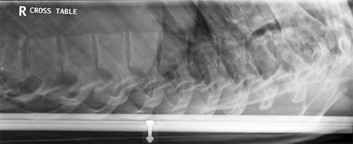
The breathing exposure technique is usually associated with lateral thoracic spine radiography. The same technique can be employed for all torso spine plain film imaging.
The breathing exposure technique is usually associated with lateral thoracic spine radiography. The same technique can be employed for all torso spine plain film imaging.
Imaging the Thoraco-lumbar Junction
The requesting doctor's intentions are occasionally not clear when a request is received for radiography of the thoraco-lumbar spine- is the referring doctor expecting all of the thoracic and lumbar spine imaged or is the intention to image the region of the thoraco-lumbar junction only? If the intention is for imaging of the thoraco-lumbar junction, how many thoracic and lumbar vertebrae should be included? If the referring doctor's intention was to have all of the thoracic and lumbar spine demonstrated, that is what he/she should have requested- i.e. thoracic and lumbar spine radiography. It is more likely that the referring doctor's intention was for the region of the thoraco-lumbar junction to be imaged. The number of thoracic and lumbar vertrebra to be included can usually be gleaned from a consideration of the patient's history and from talking to the patient about their presentation.
John H. Harris et al (The Radiology of Emergency Medicine, 3rd Ed, 1993,p 247, Williams and Wilkins) define the thoraco-lumbar spine to include "T12 through L2". The authors suggest that "... a further reason for considering these transitional vertebrae [i.e. thoraco-lumbar vertebrae] as a separate portion of the spine is the Chance fracture, which almost exclusively involves one of these vertebrae. The thoracolumbar area is that portion of the spine most susceptible to injury, and approximately two-thirds of all spine injuries occur in his region".
If the vertebra of interest (i.e. fracture follow-up) is at the T12/L1 level, consideration of exposure technique can be critical for the lateral view, particularly when using film/screen technique. If the radiographer's intention is to employ a thoracic spine exposure technique, exposure on full inspiration may push the diaphragm down enough to not overlie the vertebra of interest. Conversely, a lateral lumbar spine exposure will fail if the vertebra is within the lungfields. Furthermore, the automatic exposure device (AED) may not provide an ideal exposure if the lungfields are partly overlying the central chamber of the AED.
In cases of follow-up on spinal fractures, the beam should not be collimated to the vertebra of interest in the lateral projection. The referring doctor will require an appreciation of the fracture's affect on the normal lumbar lordosis/thoracic kyphosis.
Collimated views of the Vertrebra of Interest
A tightly collimated radiographic demonstration of a vertebra with an equivocal finding can assist in diagnosis. The tightly collimated beam will reduce scatter radiation and will improve the diagnostic value of the image. In addition, the vertebral anatomy of interest will not suffer from the distortion associated with imaging by the more peripheral oblique rays.
Horizontal Ray Technique
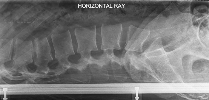
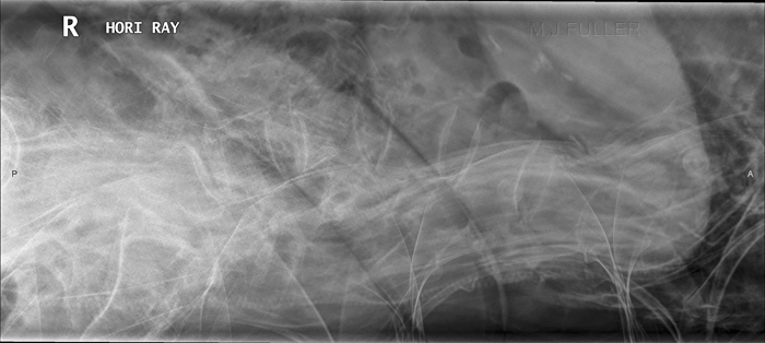
Digital Double Dipping Case StudyThe horizontal ray lateral technique is commonly employed in patients who are unable to roll into the lateral position and/or in patients who have a possibility of an unstable spinal injury.
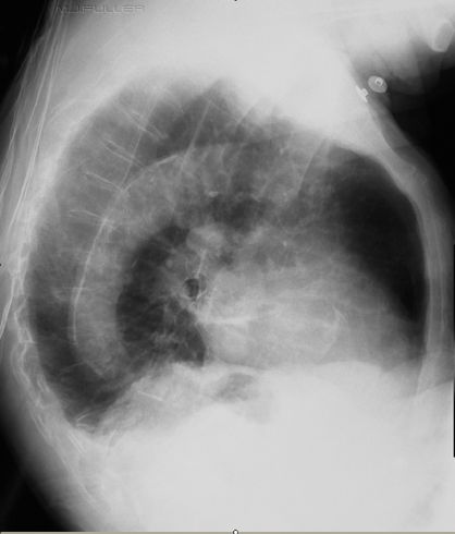
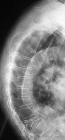
Is the Fracture Stable?Patient HistoryThis elderly patient presented to the Emergency Department with spontaneous onset of chest and thoracic spine pain. The patient has a history of COAD and osteoporosis.
TechniqueThe radiographer has performed an erect PA and lateral X-ray examination using the AEC. The lateral chest image is shown below.
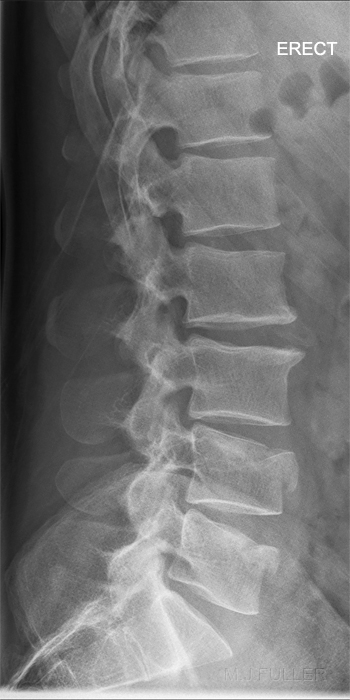
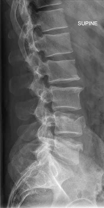
Erect and Supine Functional Views
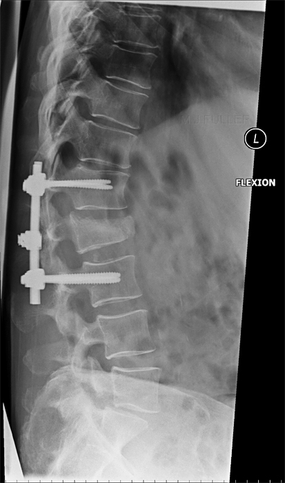
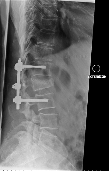
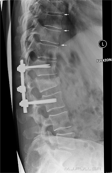
Is there any Retropulsion of Bony Fragments?The stability of the fracture can be assessed with erect and supine lateral views or flexion and extension lateral views.
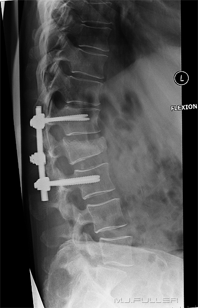
Flexion and Extension Functional ViewsThe stability of the fracture can be assessed with erect and supine lateral views or flexion and extension lateral views.
This patient has a wedge fracture of L2 stabilised by pedicle screws This patient has a wedge fracture of L2 stabilised by pedicle screws
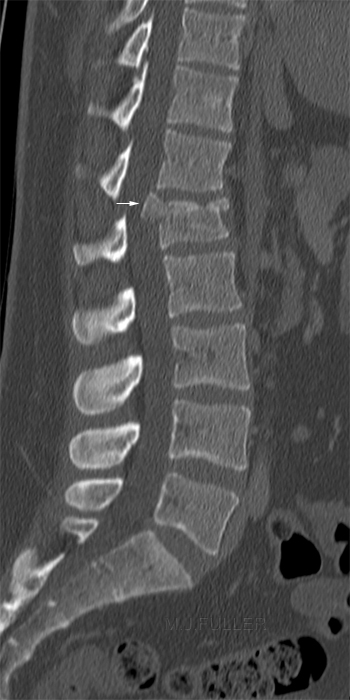
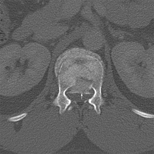
Retropulsion of bony fragments into the patient's spinal cord is clearly a matter for accurate assessment. Whilst retropulsion of bony fragments into the spinal cord can sometimes be seen on lateral plain film views, CT scanning is the preferred imaging technique. The harm caused by the retropulsed bony fragments will depend on many factors including site- a thoracic retropulsed bony fragment will be more likely to cause cord damage than a mid/low lumbar retropulsed bony fragment which is below the conus.
Intervertebral disc herniation posteriorly cannot be assessed on plain film imaging.
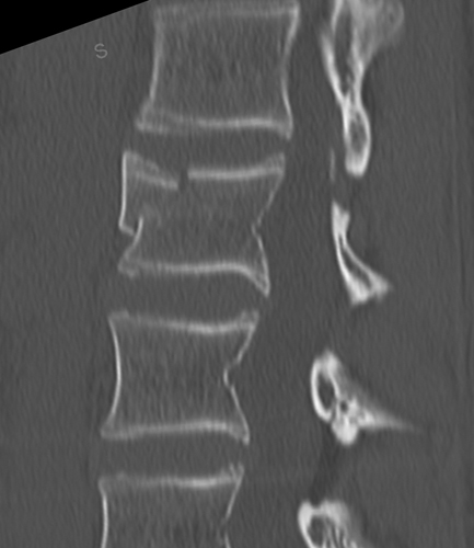
Saggital CT lumbar spine with vertebral body fracture. There is significant retropulsion of a bony fragment. Same patient axial CT. Retropulsed fragment arrowed.
<a class="external" href="http://radiology.rsna.org/content/153/3/769.full.pdf" rel="nofollow" target="_blank">Jose Guerra, Jr., M.D. Steven R. Garfin, M.D. and Donald Resnick, M.D.</a>
<a class="external" href="http://radiology.rsna.org/content/153/3/769.full.pdf" rel="nofollow" target="_blank">Vertebral Burst Fractures: CTAnalysis of the Retropulsed Fragment”</a>
<a class="external" href="http://radiology.rsna.org/content/153/3/769.full.pdf" rel="nofollow" target="_blank">Radiology 1984; 153: 769-772</a>
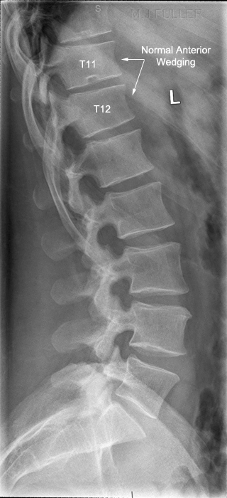
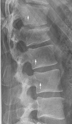
How Much Wedging is normal?
"Vertebral body height:
| ||
| <a class="external" href="http://www.dynamicchiropractic.ca/mpacms/dc_ca/article.php?id=51049" rel="nofollow" target="_blank">http://www.dynamicchiropractic.ca/mpacms/dc_ca/article.php?id=51049</a> |
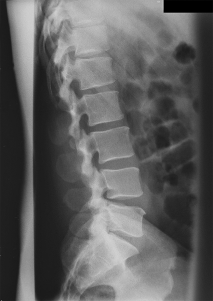
This is a normal lateral lumbar spine (except for pars defects at L5). Note the normal slight anterior wedging of the vertebral bodies at T11 and T12.
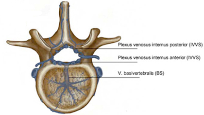
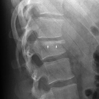
Venous Impression of the Basivertebral Veins
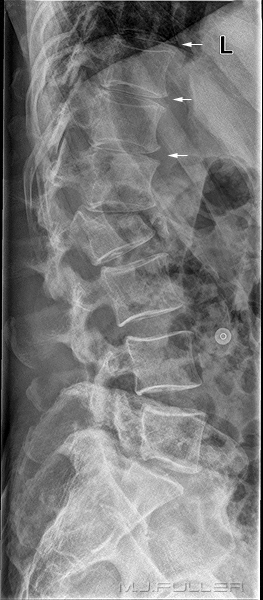
<a class="external" href="http://www.springerlink.com/content/g718n3652w216626/" rel="nofollow" target="_blank">SilkeBecker and BronekBoszczyk, Balloon Kyphoplasty, 2008</a>The arrowed structures are the ostia of the basivertebral veins
Is the Fracture Old or New?
This is a commonly asked question. It can be difficult/impossible to determine radiographically whether a compression fracture of a thoracic or lumbar vertebral body is old or new. Osteopenic compression fractures can be very difficult, if not impossible, to determine acuity radiographically. Radionuclide bone scanning can show a spinal fracture as a 'hot spot' for up to 18 months post-injury and is therefore not useful in determining acuity. The determination of wedge fracture acuity is commonly an on-balance consideration, with clinical considerations often playing a significant role.
When attempting to determine wedge fracture acuity, the following are a few considerations that should be borne in mind.
Zone of Compression
When a vertebral body in compressed with an axial force, the bony trabeculae are compressed together. This causes a sclerotic band adjacent to the compressed endplate which represents the summation density of trabelular impaction. Whilst this does present valuable evidence of a new fracture, the sign is unreliable- that is- some new compression fractures will not show this feature. Of particular note, osteopenic wedge fractures usually will not show this feature.
Sharp/remodelled Anterior contour
Paraspinal Line
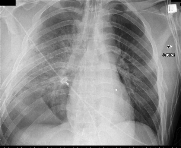
There is extreme widening/prominence of the left paraspinal line (arrowed) caused by haematoma. This is a soft tissue sign of spinal trauma.
CT Scan
It is usually not difficult to establish if a fracture is old or new on CT scanning. This fracture has sharp bony edges consistent with a recent injury.
MRI Scan
Radiography of Wedge Fractures in Osteoporosis
"In osteoporosis, osteoclastic activity exceeds osteoblastic activity, resulting in a generalized decrease in bone density. The osteoporosis weakens the bone to the point that even a minor fall on the tailbone, causing an axial load or flexion, results in one or more compression fractures. The fracture is usually wedge shaped. Without correction, a wedge fracture invariably increases the degree of kyphosis." <a class="external" href="http://emedicine.medscape.com/article/309615-overview" rel="nofollow" target="_blank">http://emedicine.medscape.com/article/309615-overview
</a>
Getting Through the Joints
A 2004 AJR article <a class="external" href="http://www.ajronline.org/cgi/reprint/183/4/949" rel="nofollow" target="_blank">( Leon Lenchik, Lee F. Rogers, Pierre D. Delmas, Harry K. Genant, Diagnosis of Osteoporotic Vertebral Fractures: Importance of Recognition and Description by Radiologists, AJR:183, October 2004)</a> reported high levels of missed/unreported vertebral fractures in osteoporotic patients and suggested that radiography failure was a contributing causal factor. When the Radiologists is attempting to make a call on a wedge fracture that is marginal, it is not helpful if he/she is assessing a vertebral body that is not in a true lateral position. Whilst this is sometimes unavoidable, a careful assessment of the curve (or otherwise) of the patient's spine in the lateral position and the setting of a matching FFD/SID will help to avoid this problem. One of the most common errors in lateral spine radiography is a failure to employ a long enough FFD/SID when the patient has little or no lateral curve of the spine
Adjusting the FFD/SID to suit the Patient Body Habitus
There is a tendency for the intervertebral disc spaces to be demonstrated best at the centre of the image and worst at the periphery of the image (see left). The reason for this phenomenon is that the central intravertebral disc(s) tend to be imaged in true profile while the divergence of the X-ray beam tends to not meet the peripheral lumbar vertebrae at right angles. This might appear to be unavoidable, but much can be done in terms of radiographic technique to overcome this problem.
The chiropractors largely avoid this problem by performing all spine radiography with the patient erect at 180cms. This is not always possible (e.g. trauma patients) requiring an alternate approach.
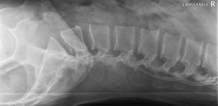
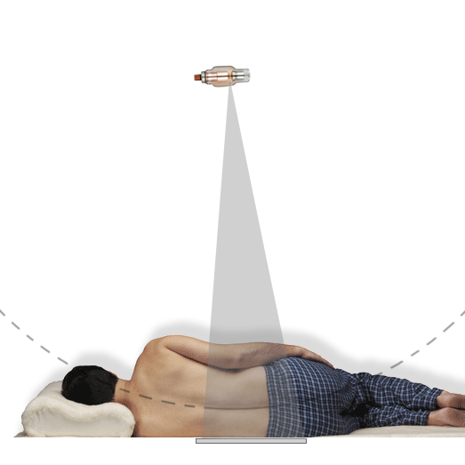
<a class="external" href="http://www.made-in-china.com/image/2f0j00JCPTQLuWghqBM/X-Ray-Tube-CT-18-X762-.jpg" rel="nofollow" target="_blank">and http://www.made-in-china.com/image/2f0j00JCPTQLuWghqBM/X-Ray-Tube-CT-18-X762-.jpg</a>note- this image has been used for illustrative purposes and does not represent a radiographic lateral lumbar spine position.When performing lateral lumbar spine radiography using the table bucky/IR, the patient should be positioned in the rolled lateral position and a careful assessment of the shape of the patient's lumbar spine should be made in this position. You are aiming to set the FFD/SID to a distance where the lumbar spine describes the arc of a circle centred at the focal spot.
I have heard of a radiographer who used a piece of string attached at the level of the focal spot of the X-ray tube and a pencil at the level of the patient's spine and moved the pencil though an arc to ensure that every spinous process was aligned with the arc of a circle centred at the focal spot. This is an extreme technique but, nevertheless, illustrates the principle.
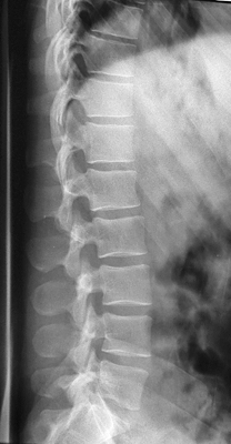
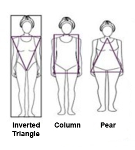
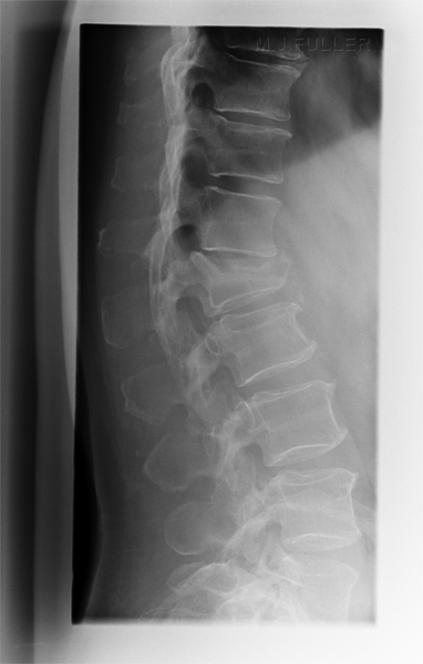
If you are successful, you should produce an image like this (note that this image is collimated to include the thoraco-lumbar junction) The patient's body shape will provide significant clues as to the likely shape of the patient's lumbar spine in the rolled lateral position.
Lateral Lumbar Spine Exposure Technique
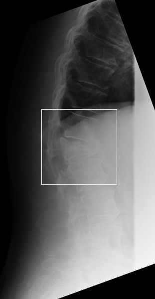
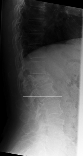
This patient was referred on multiple occasions for follow-up imaging of a L1 crush fracture.
Comment
Wedge fractures are an important plain film finding. Good radiographic technique can make the difference between diagnosis and misdiagnosis.
... back to the Wikiradiography home page
...back to the Applied Radiography home page
