Artifacts and Artefacts
Introduction
I have alluded to a transatlantic spelling issue in the title. The North Americans have traditionally called it an "Artifact" and the British have spelled it with an "e" as in "Artefact". At least they have largely decided what to do- here in Australia we are just confused on the subject. I am going to use the "i" version but for no particularly good reason. For more information on the spelling issue click <a class="external" href="http://www.worldwidewords.org/qa/qa-art1.htm" rel="nofollow" target="_blank">here</a>
Artifacts can usefully be divided into film artifacts associated with developer-fixer/film-screen (DFFS) radiography and digital artifacts associated with digital radiography (CR and DR). I am not considering the "coins in the pocket" type artifacts here.
Developer-fixer/film-screen (DFFS) radiographyStatic Artifact
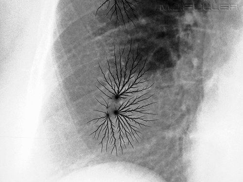
If there was to be a beauty competition for artifacts, here is your winner. Its beauty belies its potential to spoil an otherwise successful radiograph. Static artifact is caused by an electrical discharge, usually from your finger to the film. The artifact appears to have two components. Firstly, there is an amorphous graduated fog which can be seen radiating out from the black dot at the origin of the artifact. This is simply the radiating light fog from the light associated with the initial spark from your finger to the film. Secondly, there is the discharge of static electricity forking out from the initial discharge point.
Preventing static artifacts was at times difficult. Grounding your hand on a metal object before you remove the film from the cassette would probably avoid the static discharge. The frequency of static artifacts might also depend on floor coverings and your footwear.
Digital RadiographyAliasing Artifact
This is quite a complicated subject although the concept of an interference pattern is elegantly simple. For a very comprehensive discussion of the subject refer to the document titled "Stationary Grids for Kodak Computed Radiography" by Xiouhui Wang, Ph.D., and
David H. Foos, M.S. This includes a very comprehensive explanation of the subject and is well worth the effort involved in finding it. I couldn't find it on the WWW but should be available from Kodak if you ask nicely.
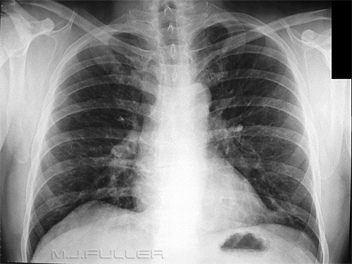
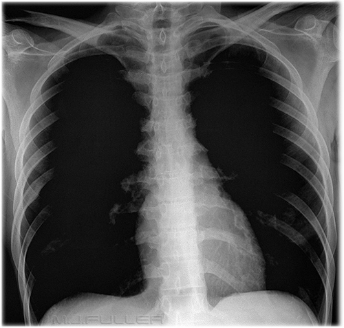
If you examine this PA chest radiograph closely you will notice that it has a subtle vertical banding pattern, particularly in the right hemithorax. This is likely to be caused by incompatibility of the CR system with the grid frequency of the wall bucky. This artifact could be thought of as a form of <a class="external" href="http://en.wikipedia.org/wiki/Diffraction_grating" rel="nofollow" target="_blank">diffraction grating</a> artifact or interference pattern. To avoid this artifact, you could place the cassette in the bucky in a portrait orientation or you can change the grid to a different frequency that is compatible with the particular CR system that is being used (grid frequency higher than scan frequency).
NoteThe grid ratio is defined as the height of the grid strip divided by the thickness of the interspace material.
The grid frequency is defined as the number of grid strips or lines per inch or per centimetre.
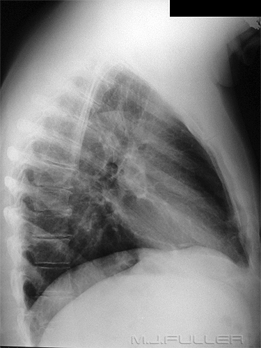
There is a special case of grid aliasing known as a "beat pattern" and I suspect that this is an example of a "beat pattern" . (happy to be corrected on this!)Note that the lateral view on the same patient does not appear to suffer from the same banding artifact. This is a result of the cassette orientation- when the cassette is placed in the cassette tray in the portrait orientation, the grid lines and the CR laser scanning lines are orientated at right angles
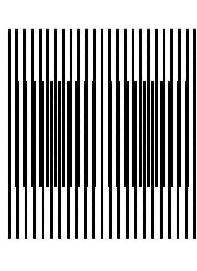
This image is an example of an interference pattern. Imagine the longer parallel lines to be the grid lines and the shorter lines to be the laser reader path lines. For an interference pattern to occur, the lines must be at different spacings or frequencies.
If you squint at the image you can see the banding effect.
For more information on interference patterns see Jeremy Enfinger's excellent blog on this subject at <a class="external" href="http://bloggingradiography.blogspot.com/2008/01/to-grid-or-not-to-grid.html" rel="nofollow" target="_blank">http://bloggingradiography.blogspot.com/2008/01/to-grid-or-not-to-grid.html
</a>
Scratches
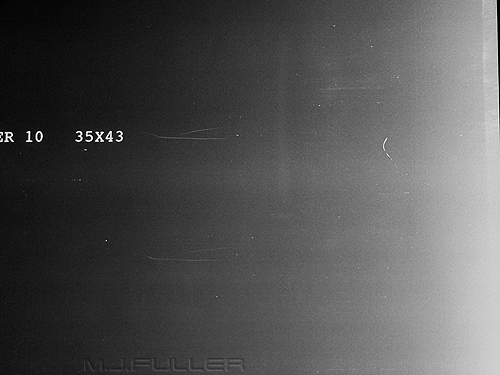
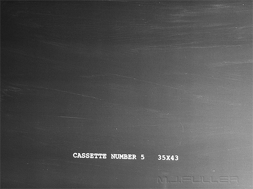
This is a low exposure test image taken with a CR cassette that was thought to contain scratches. Note that the scratches are not on the "film", they are on the photostimulable phosphor plate that is scanned by the plate reader.
Solution- new photostimulable phosphor plateCleaning Marks
Over Exposure
This image is taken using a CR system. The image is overexposed to a point where much of the lungfields contain no information. Because the pixel values are at infinity, no amount of window manipulation will reveal anatomical structures.
Clearly, this image needs to be repeated.
Defective Transport of the Storage Phosphor Plate
This image is taken on a CR system. There is a horizontal artifact across the upper third of the image. It appears to involve bones and soft tissues but does not involve the black post-processing auto-coning.
? caused by defective transport of the storage phosphor during laser scanning.
DR Grid Up-side-down
This image is taken on a DR system.
There is are vertical banding artifacts.
The grid was found to be up-side-down. The image was retaken with the grid orientated correctly without repetition of the artifact.
ConclusionArtifacts such as those described above can result in an image being repeated. An awareness of common artifact appearances can assist in finding a timely diagnosis and remedy. Minimising the number of repeat images from artifacts will improve efficiency and reduce patient radiation dose.
Further Reading
Jorg W. Oestmann, MD, Matbias Prokop, MD, Cornelia M. Schaefer, MD, Michael Galanski, MD Hardware and Software Artifacts in Storage Phosphor Radiography. Radiographics, September 1991
Stationary Grids for KODAK Computed Radiography, Xiouhui Wang, Ph.D., and David H. Foos, M.S. Health Imaging Division
EASTMAN KODAK COMPANY Rochester, New York 14650 USA (unpublished)
....back to the applied radiography home page here
