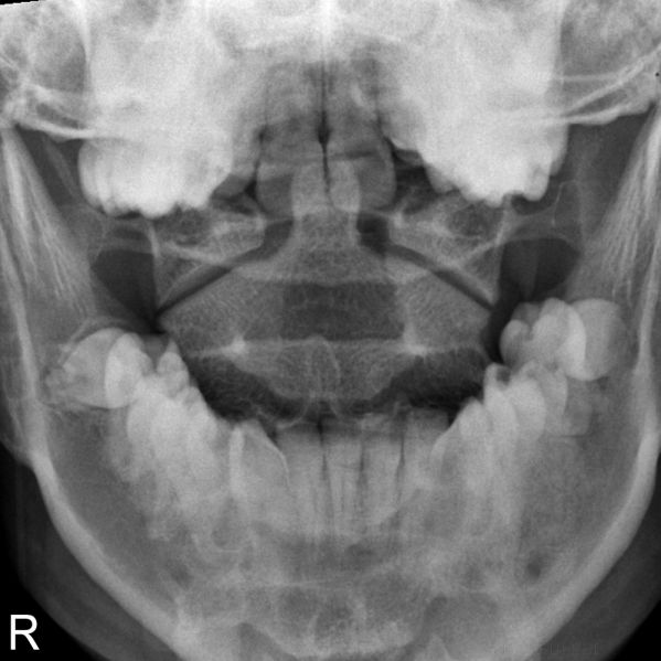
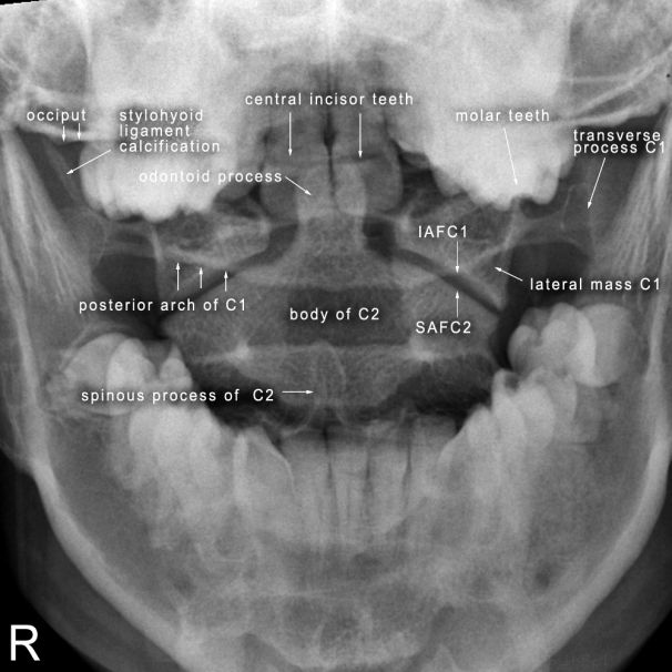
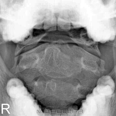
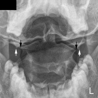
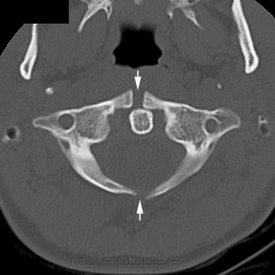
The AP Odontoid Peg Projection
AnatomyThe AP open mouth projection of the odontoid peg can be troublesome. The main difficulty arises from the fine line between successful positioning and unsuccessful positioning.
Radiographic Technique
There are a number of objectives when performing the AP open mouth odontoid peg view
- superimpose the outer table of the occiput of the skull with the patient's central incisors
- position the patient's head in a true AP position
- ensure the patient's mouth is open as wide as possible
- cone to include the anatomy of interest
- don't injure the patient in the process
1. Superimpose the Outer Table of the Occiput of the Skull with the Patient's Central Incisors
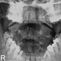
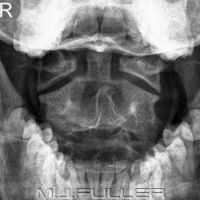
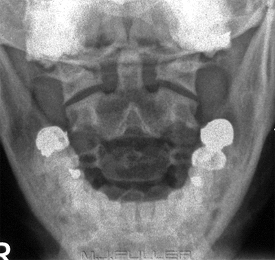
Case 1: The patient shown below is endentureless. When the hard palette (there are no central incisors to line up with) is superimposed over the occiput it can be seen that most of the odontoid peg could be visualised in an open mouth odontoid peg view. This is the best case scenario.
| Case 1 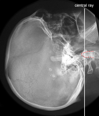 |
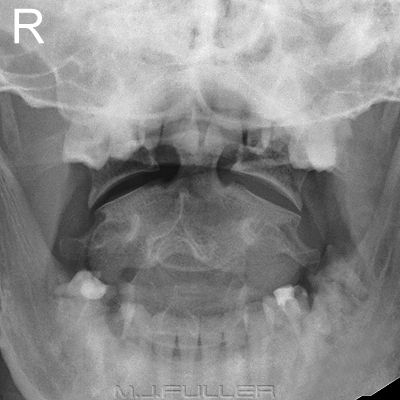
Case 2: This patient is the worst case scenario. A line drawn between the patient's upper dentition and the most inferior point of the occiput passes through the base of the dens. The chances of clearly demonstrating the odontoid peg in a conventional AP projection are minimal.
Case 2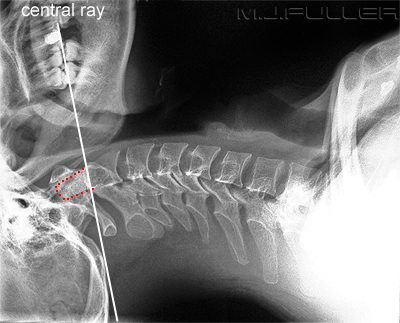 | |
Most patients will have more convenient anatomy that will allow for the successful demonstration of the odontoid peg in the AP projection. Errors in positioning of the patient's head are shown below
2. Position the patient's head in a true AP position
3. Ensure the Patient's Mouth is open as Wide as Possible
Image 1 Image 2
4. Cone to Include the Anatomy of Interest
Image 1 Image 2
5. Don't injure the Patient in the Process
Trauma cervical spine imaging is potentially dangerous to the patient with an unstable cervical spine fracture. A healthy level of paranoia is a good thing. Immobilisation of the patient's head and neck is more important than achieving the correct position for imaging. It is very easy to fall into the trap of "goal displacement" wherein producing diagnostic images displaces the goal of patient safety.
The most hazardous radiographic practice in a trauma setting is spinal flexion and extension views. Flexion and extension views of the cervical spine in trauma patients should only be done under the express (written) request of a medical officer (preferably a consultant neurosurgeon). If in doubt, the medical officer requesting the flexion and extension views should be asked to perform the positioning. If in doubt- check......if still in doubt, don't do them!
Forcibly opening an unconscious patient's mouth to perform a peg view is also hazardous. You should undertake this procedure under medical supervision and be sure that the object used will not be swallowed or inhaled by the patient and will, preferably, not produce an artifact.
Supplementary Techniques
On some patients you will not be able to achieve a satisfactory AP demonstration of the odontoid process. Here are a few alternative techniques that could be considered.
The Occipitomental Projection
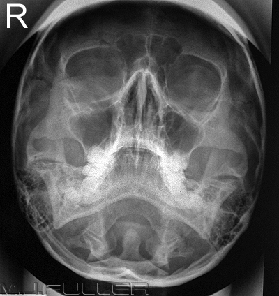
You may have noticed that you can visualise the odontoid peg on the occipito-mental (OM) image of the facial bones. A collimated OM projection can be considered as an alternative technique for imaging the odontoid process. The disadvantage of this projection is that the odontoid process and related anatomy are projected over the occiput of the skull. If you're lucky, the foramen magnum will be conveniently positioned.
Important note: extending a patient's neck to achieve an OM position is contra-indicated in a trauma patient. X-ray beam angulation can achieve a similar result.
Fuchs View
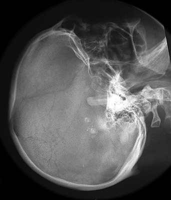
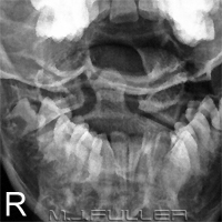
This image is a collimated OM for the odontoid process (Fuch's View). The original collimation marks are displayed.
A frequent failing of this projection is underexposure (this image is slightly underexposed). The exposure technique should be as for an OM projection of the facial bones rather than an AP cervical spine projection.
Further information here <a class="external" href="http://bloggingradiography.blogspot.com/2007/05/odontoid-trouble.html" rel="nofollow" target="_blank">http://bloggingradiography.blogspot.com/2007/05/odontoid-trouble.html</a>
Moving Jaw Technique
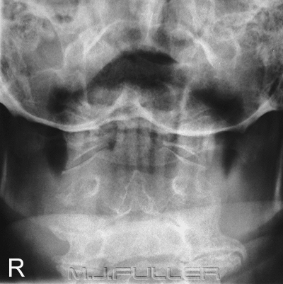
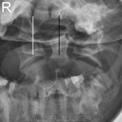
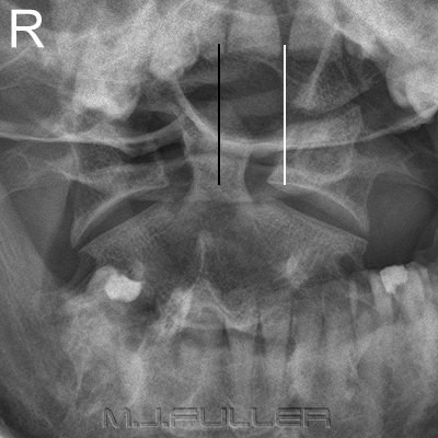
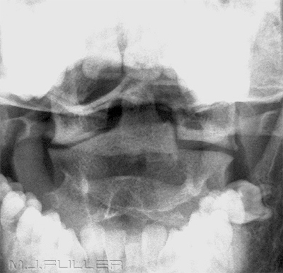
It is possible to blur out the mandible using a moving jaw technique. This is a deliberate use of movement unsharpness. This is not a technique that would be frequently employed, but may be useful to consider when all else fails. The vertical lines are the blurred lower incisor teeth.
Inclusion on AP Cervical Spine Projection
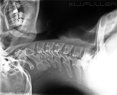
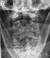
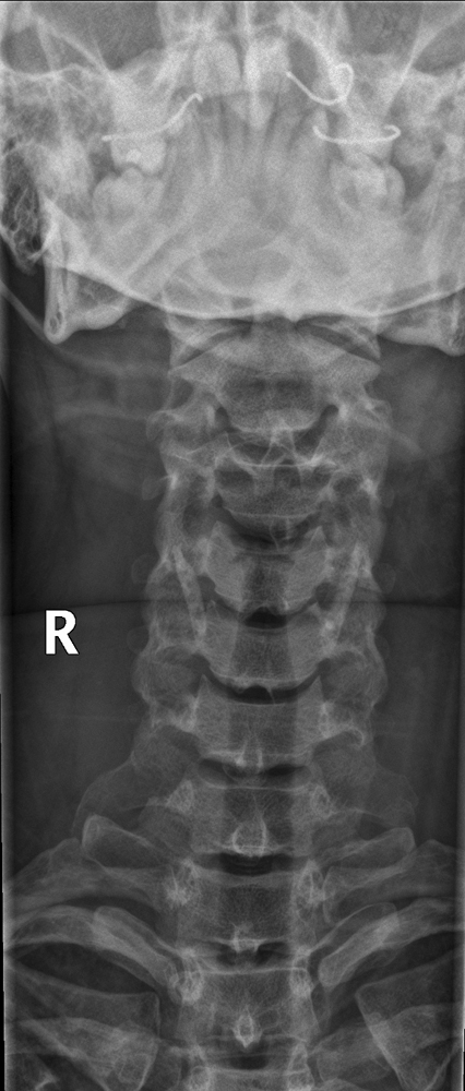
It may be possible to include the C1/C2 articulations and the odontoid process on the AP cervical spine image. The neck extension associated with the fitting of a hard cervical collar may achieve this result without any special effort.
Short FFD Technique
Some radiographers advocate the use of a short FFD to increase the chances of displaying the alignment of the lateral masses of C1 and C2.
Obliques
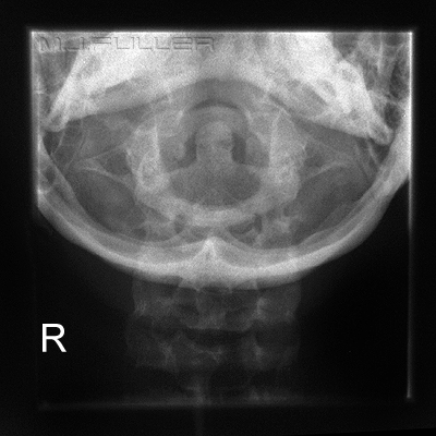
This AP view of the odontoid peg demonstrates asymmetry of the lateral masses of C1 with respect to the dens. This asymmetry is evident despite the fact that the patient's skull appears to be in a true AP position. Note that the upper central incisor teeth are symmetrically distributed with respect to the dens.
To gain additional confidence that the appearance is physiological rather than pathological, oblique projections can be of assistance.
Artifacts
The LPO position in particular shows evidence of symmetry of the C1 lateral masses with respect to the dens and with respect to the body of C2. This additional information needs to be considered in the context of:
- clinical signs (eg parasthesia, head control, pain)
- mechanism of injury (eg high speed MVA)
- evidence of injury demonstrated on the other cervical spine projections
- soft tissue signs of injury.
It is not uncommon for the AP odontoid peg image to be marred by artifacts. Whilst some are unavoidable, a knowledge of common artifacts can be helpful.
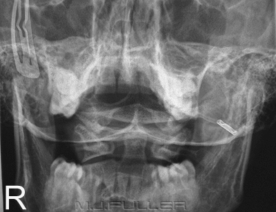
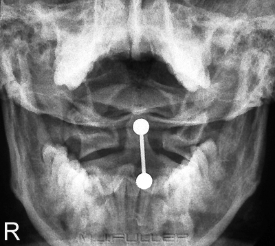
| | This artifact is a tongue stud. The patient is unlikely to be willing to remove this stud but it is worth asking regardless. |
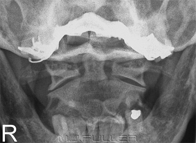
| | Dental plates and dentures should be removed where possible. Note that the superimposition of the posterior arch of C1 over the base of the odontoid peg can be mistaken for a fracture- beware, this patient does not have a type III fracture of the dens. |
Normal Variants
Normal anatomical variants involving the upper cervical spine are not rare.
Conclusion
This is an example of asymmetrical lateral masses of C2. There are many different known normal anatomical variants of the C2 lateral masses.
Incidental finding of absence of the odontoid process
The AP odontoid peg view can be a challenge for radiographers. A sound knowledge of normal anatomy, pathological appearances and positioning techniques is essential.
....back to the applied radiography home page here
